





Description
Product Introduction
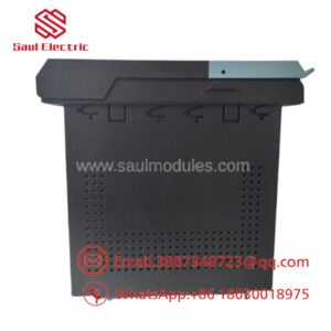
The GE DS200SDCIG2AHB functions as the primary DC Power Supply and Instrumentation Board (SDCI) within the GE Speedtronic Mark V turbine control framework and DC2000 drive systems. Positioned within the drive chassis—typically seated directly behind the primary SDCC control board—the SDCI card provides power distribution and vital signal conditioning loops required for high-power DC drive regulation.
The SDCIG2AHB iteration manages power conversion rails (+5 V DC, ±15 V DC, ±24 V DC, and 115 V AC) while processing armature current/voltage feedback, field current levels, and AC line phase sequence telemetry. Equipped with onboard current-limiting protection fuses and adjustable hardware jumpers (JP1, JP2, SW1), it acts as an essential hardware bridge between high-voltage power components and low-voltage control processors.
Key Technical Specifications
| Parameter | Specification |
| Manufacturer | General Electric (GE) |
| Part Number | DS200SDCIG2AHB |
| System Compatibility | Speedtronic Mark V / DC2000 Drive Systems |
| Functional Acronym | SDCI (DC Power Supply and Instrumentation Board) |
| Mark V Grouping | Group 2 (G2) |
| Power Output Rails | +5 VDC (4A), ±15 VDC (0.4A), ±24 VDC, 115 VAC (0.4A) |
| Protection Circuitry | 6x Onboard Fuses (FU1–FU6) with fault-indicating LEDs |
| Hardware Adjustments | JP1 (MD Control Source), JP2 (AC Contactor Drop-Out), SW1 (CT Burden Select) |
| Manual Reference | GEI-100173 |
| Revision Level | Functional A, H |
Application Scenarios & The “Trench” Experience
During high-load motor operation on a heavy industrial DC drive, an AC power line surge causes an overcurrent condition on the armature feedback loop. The primary drive trips on a voltage sense fault. Diagnostic troubleshooting reveals that a fuse blew on the SDCI board and an internal signal amplifier path for the current transformer (CT) feedback burned out. Technicians isolate power, tilt the front SDCC rack forward, unclip and replace the failed card with a bench-verified DS200SDCIG2AHB, duplicate the original CT burden switch (SW1) and jumper configurations, and safely re-energize the drive system.
- DC2000 Industrial Motor Drives – SCR Gate Driving & Field Control – Directs pulse signals to SCR firing bridges and monitors field current feedback.
- Gas & Steam Turbine Auxiliary Drives – Armature & Line Telemetry – Measures AC/DC line voltage, armature current, and phase sequence for system protection.
- Power Plant Power Distribution – Regulated Bus Supply – Delivers isolated DC logic power to adjacent control modules in the Mark V cabinet.
Transparency SOP: Quality Assurance & Testing
We don’t just ship boxes; we test them on actual GE Mark V / DC2000 test racks.
- Inbound Visual & Substrate Audit: High-magnification check for burnt resistors, blown MOV surge suppressors, trace delamination, and damaged edge connectors.
- Fuse & Protection Rail Check: Continuity testing across fuses FU1–FU6 and verification of LED indicator diagnostic circuits.
- Power Output Verification: Bench testing all DC/AC power output rails (+5V, ±15V, ±24V, 115VAC) under calibrated loads to confirm regulation stability.
- Signal Conditioning Linear Check: Injecting simulated CT/PT voltage and current signals to confirm accurate feedback response and proper CT burden switch (SW1) operation.
- Anti-Static Packaging: Sealed inside thick static-shielding ESD bags with fresh desiccant packages prior to protective foam boxing.
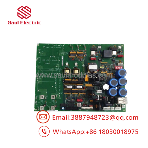
DS200SDCIG2AHB
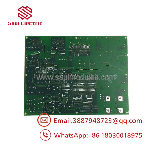
DS200SDCIG2AHB
The Veteran’s Tech Trap Guide (Crucial Value-Add)
- ⚠️ CHECK HIGH VOLTAGE BEFORE ACCESSING: The SDCI board interfaces directly with high-voltage AC lines (up to 600V AC) and motor power circuits. Always verify that main line power is locked out and perform a zero-voltage check before opening the drive enclosure or touching internal cards.
- ❗ SET JUMPERS & SW1 BURDEN SWITCH EXACTLY: The
DS200SDCIG2AHBfeatures hardware adjustments: JP1 (Control Source), JP2 (Contactor Drop-Out Time), and SW1 (CT Line Burden Select). Failing to match SW1 to your motor’s nominal DC current rating will cause inaccurate current feedback and false overcurrent trips. - ⚠️ CAREFUL WITH THE ACCORDION/PIVOT MECHANISM: The SDCI card is located behind the SDCC drive control board. Disengage the cabinet latches and carefully tilt the SDCC frame forward to access the SDCI without straining connected ribbon cables.
- ❗ INSPECT BLOWN FUSE LED INDICATORS: Before removing the board for an apparent dead rail, check the onboard LED indicators next to fuses FU1 through FU6. A blown fuse may indicate an external field short rather than a defective board.
Frequently Asked Questions (FAQ for Conversion)
Q: What does the SDCI abbreviation stand for on the GE DS200SDCIG2AHB?
A: SDCI stands for Speedtronic DC Control Instrumentation (or DC Power Supply and Instrumentation Board).
Q: Where is the DS200SDCIG2AHB board located inside the drive cabinet?
A: It is located directly behind the main SDCC (Drive Control Board) module. To reach it, you pull down the locking mechanisms on the front SDCC card cage and pivot it forward.
Q: Can a replace an older DS200SDCIG1 or DS200SDCIG2ABA board?
A: It can directly replace earlier revision Group 2 boards like DS200SDCIG2ABA. Ensure that the hardware jumpers (JP1, JP2) and the CT burden switch (SW1) are configured pin-for-pin to match your original board.
Q: Does replacing this card require software downloads or laptop flashing?
A: No. The SDCI board is an analog power supply and signal conditioning card. It holds no programmable flash memory; all setup is done via physical hardware switches/jumpers and external drive parameters.
Q: What warranty is provided with this replacement module?
A: Every unit is backed by a full 12-month replacement warranty from the delivery date, covering voltage output regulation, CT/PT feedback channels, and component execution.


 Start Chat


