





Description
Product Introduction
The GE DS200TCQCG1A is a primary Analog Signal Processor Board (TCQC) engineered for GE Speedtronic Mark V turbine control systems. Installed in the main core architecture (<R>, <S>, and <T> cores), it serves as the operational backbone for reading continuous field variables—such as pressure transducers, LVDT valve position feedbacks, and thermocouples—while providing high-speed analog control outputs.
Unlike basic discrete I/O cards, the TCQC board houses specialized analog-to-digital (A/D) conversion hardware and dedicated output drivers for electro-hydraulic servo valves. It executes real-time signal scaling and noise filtering onboard before streaming digitized process variables over the backplane to the primary Stage One processor, maintaining microsecond-level synchronization across redundant control loops.
Key Technical Specifications
| Parameter | Specification / Value |
| Manufacturer | General Electric (GE) |
| System Architecture | Speedtronic Mark V Gas/Steam Turbine Control |
| Board Functional Acronym | TCQC (Analog Signal Processor Board) |
| Input Signal Types | 4-20mA loops, 0-10VDC, LVDT/RVDT position, Thermocouples |
| Output Capabilities | Servo valve driver outputs, 4-20mA analog retrains |
| Primary Interfaces | Dual 50-pin ribbon headers (JCA, JCB), 3PL backplane connector |
| Hardware Configuration | Physical BERG jumpers for channel voltage/current range selection |
| Diagnostic Indication | Edge-mounted diagnostic LEDs (Power, Processor Active, Board Fault) |
| Memory Architecture | Socketed PROM/EPROM chips for localized firmware execution |
| Board Form Factor | Standard Mark V full-size PCB (~21.2 cm x 15 cm) |
Application Scenarios & The “Trench” Experience
The Trench Story
It’s 4:00 AM during a scheduled startup following an outage. The fuel gas control valve on a Frame 7G gas turbine begins oscillating violently during ignition, throwing “LVDT Feedback Mismatch” alarms across the HMI. The instrument techs swap the LVDT sensors, but the hunting persists. Diagnostics pinpoint a failing A/D converter chip on the legacy TCQC board that has drifted out of calibration, feeding erratic position values back to the core. With the plant facing strict grid-availability deadlines, pulling a verified DS200TCQCG1A replacement from storage stabilizes the valve feedback, eliminates signal drift, and allows smooth ignition on the next start attempt.
Industrial Applications
- Fuel Valve Servo Control: Driving electro-hydraulic servo valves and processing LVDT feedback loops for gas and liquid fuel control valves.
- Turbine Temperature Monitoring: Conditioning raw thermocouple signals across exhaust frames, bearing headers, and combustor shells.
- Process Pressure Loops: Reading compressor discharge pressure (PCD), lube oil header pressure, and hydraulic system pressure transmitters.
- Steam Turbine Inlet Control: Managing steam chest valve position loops and governor actuator outputs in combined-cycle applications.
Transparency SOP: Quality Assurance & Testing
We don’t just pull legacy boards out of a warehouse box and throw them into a crate; we validate them on live GE Mark V rack setups.
- Inbound Physical Inspection: Complete visual audit under magnification. Inspection for trace corrosion, bulging electrolytic capacitors, damaged ribbon pins, and verification of genuine OEM solder profiles.
- Anti-Static ESD Cleaning: Ultrasonic aqueous bath to remove industrial carbon dust and airborne oil film, followed by thermal drying.
- A/D Converter Calibration Check: Precision voltage and current injection across all analog input channels to test A/D conversion accuracy and linearity across 0–100% full scale.
- Live Mark V Core Testing: Board installation into a live Speedtronic Mark V test rig (
<R>,<S>, or<T>core). Verification of green LED self-test, boot cycle, and communication via the 3PL backplane connector. - Servo Loop Output Stress Test: Connecting simulated servo coil loads to verify current driver stability, response time, and zero-drift characteristics under thermal load.
- Firmware Version Logging & Anti-Static Packaging: Documenting all socketed EPROM revision tags before vacuum-sealing the board in anti-static ESD shielding.
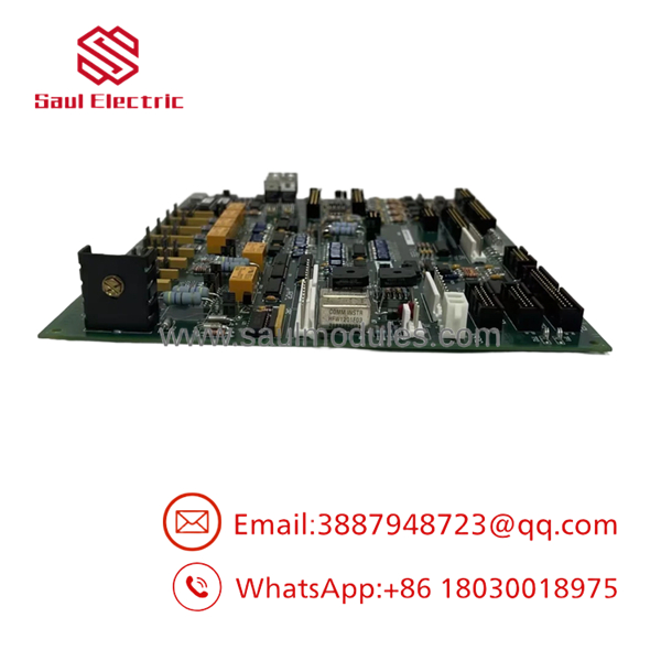
DS200TCQCG1A
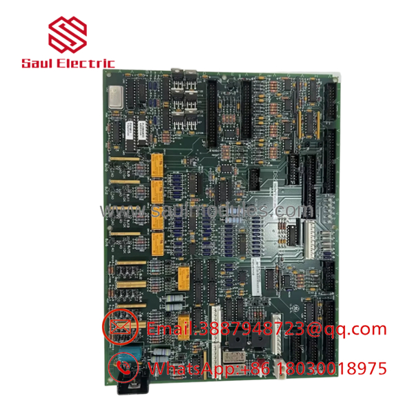
DS200TCQCG1A
The Veteran’s Tech Trap Guide (Crucial Value-Add)
⚠️ 1. The Analog Channel Jumper Trap (Current vs. Voltage Inputs)
The DS200TCQCG1A uses hardware jumpers to define whether a channel reads a 4-20mA current loop or a 0-10V voltage signal. Installing a replacement board with a channel jumper set for voltage when connected to a 4-20mA loop will cause off-scale high readings and immediate valve positioning faults.
Fix: Take a photo of every BERG jumper position on your existing TCQC board and replicate the configuration exactly on the replacement unit prior to card insertion.
❗ 2. Socketed EPROM Swapping
The TCQC board relies on socketed EPROMs to hold system-specific calibration factors and firmware definitions. Inserting a spare board with different PROM revision levels into a running core loop will trigger an HMI “I/O Config Mismatch” alarm.
Fix: Use an IC chip extractor tool to transfer your original socketed PROMs to the replacement card. Ensure the notch on the IC aligns precisely with the notch on the socket to prevent chip damage.
⚠️ 3. LVDT Zero and Span Recalibration
Even after matching jumper configurations and transferring PROMs, swapping an analog board can introduce minor component tolerance variances into sensitive LVDT position loops.
Fix: Always perform an Auto-Cal or manual zero/span calibration cycle on your fuel and inlet guide vane (IGV) valves after replacing the TCQC card before attempting a turbine start.
Frequently Asked Questions (FAQ)
Q: Can I hot-swap the DS200TCQCG1A card while the Mark V panel is powered on?
A: No. Pulling an active TCQC card disrupts the 3PL backplane and cuts analog feedback loops to the core. This will instantly trigger a system trip or drop the affected control core offline. Always power down the specific core enclosure before removing or installing the card.
Q: What is the main functional difference between a TCQC and a TCCA board?
A: While both process analog signals, the TCCA card primarily handles extended thermal inputs (like large thermocouple arrays) and general system monitoring. The TCQC (DS200TCQCG1A) is directly integrated into high-speed closed-loop control, managing servo valve outputs and critical LVDT/RVDT position feedbacks.
Q: What does the ‘G1A’ revision code at the end of the part number signify?
A: In GE Mark V part numbering, G1 represents the primary hardware group architecture, while A indicates the functional artwork revision level. The G1A specification denotes the baseline artwork layout with standard noise suppression and signal conditioning circuits.
Q: Why is my HMI showing analog input out-of-range alarms immediately after installing a new board?
A: This typically stems from one of three issues: mismatched channel jumpers (4-20mA vs. voltage mode), improperly seated 50-pin ribbon connectors (JCA/JCB), or socketed EPROMs that were not transferred from the original card.
Q: What warranty is supplied with your surplus and refurbished stock?
A: Every DS200TCQCG1A module shipped carries a full 12-month replacement warranty. If a board fails under normal operating conditions within one year of installation, we replace it immediately from our stock.




 Start Chat


