





Description
Key Technical Specifications
| Parameter | Specification Value |
| Processor Architecture | High-performance 32-bit RISC Microprocessing Core |
| Controller Platform Compatibility | GE Speedtronic Mark V Control System Matrix |
| Sustained Input Current Draw | 1.5 A nominal rated load at +5 VDC logic rail |
| Logic Supply Tolerance | Accommodates standard 85–264 VAC panel distribution setups |
| Memory Expansion Capacity | Dual firmware EEPROM sockets + specialized onboard DIMM slot |
| Onboard Network Interfaces | High-speed ARCNET local link, COM1 (R Core Monitoring), COM2 |
| Backplane Interconnect Ports | J1 and J2 STCA Core-Bus interface connector blocks |
| Onboard Mass Storage Bus | Legacy 40-pin parallel IDE header channel |
| Operating Thermal Windows | −40 to +70°C |
| Atmospheric Shielding Configuration | Standard conformal moisture/dust protective board coating |
| Board Geometry Profile | 203.2 mm x 228.6 mm x 76.2 mm |
| Net Hardware Mass | Approximately 1.76 lbs (0.80 kg) |
Product Introduction
The GE Speedtronic DS200UCPBG6AFB functions as the primary real-time calculation core for the Input/Output Engine inside General Electric Mark V turbine control system panels. Purpose-built to handle execution loops under high mechanical stress environments, this 32-bit RISC processing board handles closed-loop regulation maps driving gas and steam turbine frames. It arbitrates execution metrics for precision fuel control valves, safety generator synchronous relays, and compressor guide vane actuators, processing sensor signals in millisecond cycles.
The distinct alpha-numeric model syntax “DS200UCPBG6AFB” represents a specific revision configuration critical for cross-compatibility mapping. The “G6” label designates the core generation series setup, while the “AFB” suffix tracks physical design changes: the “A” and “F” track the first and second functional component updates implemented by GE, while the “B” designates the updated physical tracking layer on the PCB assembly. By utilizing integrated ARCNET communication links, the card broadcasts deterministic peer-to-peer data blocks across the separate controller cores (\langleR\rangle, \langleS\rangle, and \langleT\rangle) to verify complete voter synchronization across triple-redundant architectures.
Installation & Configuration Guide
Stage 1: Pre-Installation Preparation (Estimated Time: 20 minutes)
- ⚠️ Safety First: Ensure the entire Mark V controller panel core housing is completely isolated and powered down. Never pull processing assets while the system backplane logic rails are energized; doing so will cause voltage arcs that can destroy adjacent memory and analog processing chips.
- Tools Required: Grounded static-control ESD wrist strap, precision chip extraction extraction kit, needle-nose pliers, and a terminal laptop running GE Mark V Control Design configurations.
- Firmware Preservation: New replacement boards ship without firmware PROMs in their sockets. You must carefully migrate the original socketed EEPROM modules from your old card to the new one to preserve the turbine’s core calibration profile, node IDs, and logic arrays.
Stage 2: Removing the Old Module (Estimated Time: 10 minutes)
- Ensure your static-control wrist strap is securely connected to a bare metal grounding point on the control cabinet frame.
- Label and disconnect all peripheral ribbon cables, including the IDE interface link, the COREBUS lines on J1/J2, and the ARCNET communication coax lines.
- Loosen the perimeter card retaining fasteners holding the assembly inside the card rack.
- Smoothly pull the CPU board forward out of its slot guides, taking care to avoid scraping any exposed surface-mount components.
Stage 3: Installing the New Module (Estimated Time: 15 minutes)
- Extract the new surplus DS200UCPBG6AFB module from its static-shield wrap while maintaining full ESD protection protocol.
- Using a specialized chip extraction tool, gently lift the firmware PROMs out of the sockets on the old board and insert them into the matching sockets on the new board. Ensure the notch on each chip aligns with the orientation mark on the socket to avoid pin damage upon power-up.
- Slide the card into the chassis slot tracks until the rear edge pin layout seats securely into the backplane mother-grid.
- Tighten the retaining screws to lock the card against mechanical cabinet vibrations. Reconnect the J1, J2, and communication ribbon harnesses to their designated ports.
❗ Configuration Check:
[ ] Transferred PROM modules are fully seated and oriented in the correct direction.
[ ] J1 and J2 COREBUS ribbon cables are locked securely onto their matching headers.
[ ] Grounding terminal connections are verified before re-energizing the system panel.
Stage 4: Power-On & Testing (Estimated Time: 15 minutes)
- Re-engage the primary panel input power loops to boot up the I/O engine core.
- Watch the faceplate diagnostic LEDs execute their power-on self-test (POST). The status lights should step through initialization codes and settle into a normal, synchronized running pattern.
- Launch your engineering workspace to confirm that the \langleR\rangle, \langleS\rangle, and \langleT\rangle cores achieve healthy voter logic sync without flagging communication frame drop alerts.
- Verify from the system log that the ARCNET transmission interface is actively routing real-time telemetry packets across the internal network ring.
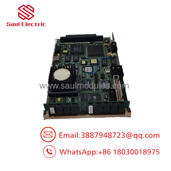
- DS200UCPBG6AFB
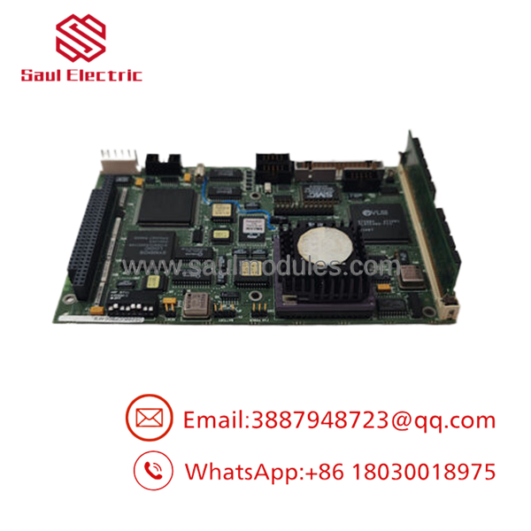
- DS200UCPBG6AFB
Strategic Quality Control & Inspection Process
To maintain reliability for critical legacy infrastructure nodes, every surplus and reconditioned Mark V processor board passes through a rigorous, multi-point quality validation protocol.
- Inbound Traceability & Visual Micro-Audit: Build revisions are checked against known factory schematics. The board structure is examined under high magnification to confirm there are no trace hairline fractures, solder fatigue, or signs of heat stress on the logic components.
- Component Testing & Power Rail Verification: The board is benched to evaluate performance across its logic gates. We check the onboard current draw profiles at the +5 VDC rail boundaries to verify that internal voltage regulators operate within precise engineering tolerances.
- Live Speedtronic Control Loop Emulation: The DS200UCPBG6AFB is installed into a functional Mark V testing rack configuration. We run full application cycle simulations—injecting simulated turbine speed deviations and high-speed valve control tasks—to confirm that the 32-bit RISC processing core handles deterministic workloads within required millisecond limits.
- Master Reset & Storage Preparation: The temporary register memory zones are cleared, and the exposed socket boundaries are protected to ensure a clean configuration process when deployed at the customer site.
- ESD Sealed Containment Packaging: Following testing clearance, clean static caps are fitted over all open connector ports. The complete card is wrapped inside high-grade static-barrier shielding envelopes, cushioned within custom form-fitting shock foam inserts, and shipped in a reinforced corrugated box accompanied by its signed technicians’ quality pass report.
Frequently Asked Questions
Can this board be hot-swapped while the turbine is running?
No. The legacy Mark V Speedtronic backplane does not support live hot-swapping of central processing or core I/O engine boards. Removing or inserting the card while control power is applied can cause voltage spikes on the logic bus, risking permanent damage to the CPU’s internal architecture and corrupting adjacent communication modules. Always shut down control power before servicing the card.
What happens if I forget to transfer the original PROM chips to the new board?
If you install the replacement board without transferring the original socketed firmware PROMs, the I/O engine CPU will fail to boot, and the panel display will flag a fatal system fault. The replacement board ships as clean hardware without operational code. The PROMs contain the specialized turbine parameters and application-specific settings needed to run your system.
My original card has a slightly different revision suffix like “AFA”. Can I use this “AFB” board instead?
Yes. Within the GE Mark V framework, the “AFB” revision acts as a direct, backward-compatible replacement for older functional iterations like the “AFA” version. The core processing performance, backplane dimensions, and terminal pin connections remain identical. The suffix simply indicates minor production updates and layout revisions designed to improve signal reliability over older board generations.
How does the board communicate with external SCADA systems or human-machine interfaces (HMIs)?
The board handles peer-to-peer data routing over high-speed ARCNET coax networks to coordinate with adjacent control cores within the panel assembly. For external data collection, terminal monitoring, and SCADA connectivity, it utilizes the dedicated front and rear serial COM1 and COM2 interface blocks, which connect to your facility’s master operator station or command node.
Why source a new surplus board instead of upgrading the entire turbine control cabinet?
Upgrading an entire turbine control system (such as moving from a Mark V to a modern Mark VIe platform) involves massive capital investments and extended operational downtime. It requires completely rewriting application logic, re-routing field wiring, updating facility documentation, and undergoing lengthy regulatory recertifications. Sourcing a genuine surplus board allows you to repair the existing control loop in under an hour, preserving your current software configuration and getting your operations back online quickly. Every processing module includes our 1-year independent depot replacement warranty.




 Start Chat


