





Description
Product Introduction
The GE DS200UDSAG1A (UDSA) is an I/O Display Driver and Operator Interface Board engineered for GE Speedtronic Mark V turbine control systems, EX2000 excitation panels, and Innovation Series heavy drive lineups. Mounted directly behind or adjacent to the front door operator panel, the UDSA card acts as the dedicated communications bridge between local cabinet displays (alphanumeric LCD/VFD character modules, discrete diagnostic LEDs) and the main system control core.
By handling multiplexed display refreshing, LED state latching, and local key-matrix decoding hardware-side, the UDSA offloads visual interface overhead from primary core processors. Its robust onboard logic chips buffer data signals against cabinet electrical noise, ensuring local diagnostics and live operational telemetry remain clear and accurate during heavy switching transients.
Key Technical Specifications
| Parameter | Specification |
| Manufacturer | General Electric (GE) |
| Part Number | DS200UDSAG1A |
| Functional Acronym | UDSA |
| System Compatibility | GE Speedtronic Mark V / EX2000 / Innovation Drives |
| Primary Function | Alphanumeric Display & LED Status Driver |
| Architecture | Multiplexed display driver ICs, keypad matrix decoders, ribbon bus headers |
| Interconnects | Multi-pin vertical ribbon connectors & card-edge interface headers |
| Configuration | Onboard hardware DIP switches & jumper pins (JP headers) |
| Mounting | Standoff panel mount or slide-in card cage assembly |
| Operating Temperature | 0°C to 60°C (32°F to 140°F) |
Application Scenarios & The “Trench” Experience
Picture this: It’s 3:15 AM during a critical grid synch operation. An operator walks up to a Mark V turbine panel to check local bearing temperatures, but the front door character display is scrambling into nonsense symbols and freezing up. While the turbine continues running safely on primary control loops, field operators are left blind at the local cabinet because a degraded display driver chip on the aging DS200UDSAG1A card lost its clock synchronization.
- Power Generation & Gas Turbines – Speedtronic Mark V Cabinets – Drives local operator interface panels, diagnostic LED arrays, and trip status readouts.
- Generator Excitation Systems – GE EX2000 Excitation Racks – Translates core telemetry into live voltage, current, and power factor numeric displays on the panel door.
- Heavy Industrial Paper & Rolling Mills – Innovation Series Main Drives – Controls door-mounted keypad status displays and diagnostic fault-code readouts.
Field Case Study: A combined-cycle plant experienced total readout blackout on its local EX2000 exciter display. Local key commands were ignored, forcing technicians to rely solely on remote HMI data. Swapping in a bench-tested DS200UDSAG1A surplus board immediately restored local keypad responsiveness and clean character display output, allowing local maintenance routines to proceed without delay.
Transparency SOP: Quality Assurance & Testing
An unverified display card can lead to frustrating ghost faults and false diagnostic readings. Every DS200UDSAG1A undergoes a complete 5-step validation procedure prior to dispatch:
- Inbound Micro-Inspection: High-magnification check for solder bridge fractures, trace oxidation, damaged ribbon header pins, and IC socket contact wear.
- Dielectric Isolation Check: Resistance check between logic supply rails (+5V, ±12V) and ground terminals to rule out shorted bypass capacitors.
- Live Test-Rig Power Up: Card is seated in a powered Mark V / EX2000 simulation rack to confirm proper bus initialization and clock line stability.
- Multiplexed Display & Keypad Stress Test: All display output channels and keypad input lines are continuously exercised across active display modules over a 12-hour burn-in period to verify multiplexing stability.
- Anti-Static Sealing & Packaging: Cleaned, fitted with pin covers, vacuum-sealed in a heavy ESD shielding bag, and packed in reinforced custom foam boxes.
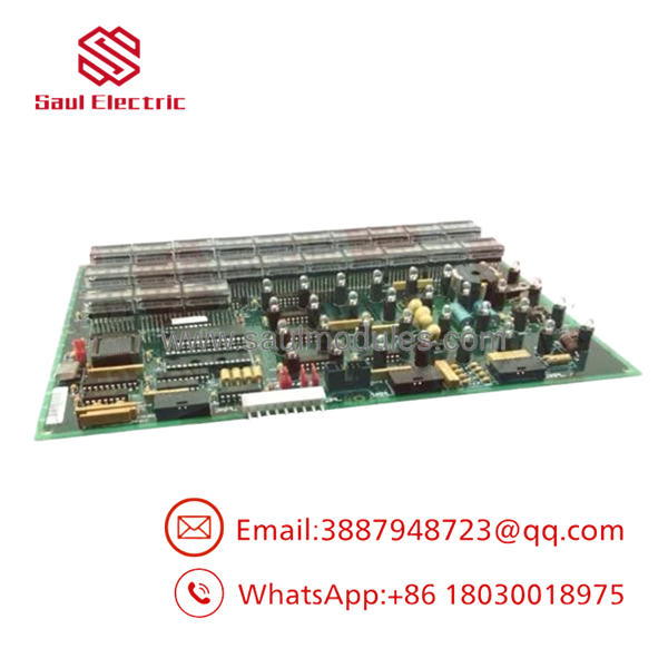
DS200UDSAG1A
The Veteran’s Tech Trap Guide (Crucial Value-Add)
⚠️ 1. Verify Jumper and DIP Switch Configurations: The UDSA board uses onboard hardware jumpers and DIP switches to select display communication baud rates, display type modes, and cabinet address IDs. Always take a high-resolution photo of your original board’s settings and match every switch and jumper block on the replacement card before powering up!
❗ 2. Handle Ribbon Cables with Extreme Care: Connecting ribbon cables can easily bend or push back header pins if misaligned. Inspect all multi-pin header connectors on the board for bent pins before pressing connectors home, and never pull directly on the ribbon cable wires during disassembly.
⚠️ 3. Inspect Socketed IC Chips: If your UDSA board uses socketed EPROMs or display controllers, make sure they are fully seated into their sockets. Thermal cycling over years in a cabinet can cause “chip creep,” where ICs slowly work themselves loose from their sockets.
❗ 4. Power Down Before Unplugging: Never hot-swap the DS200UDSAG1A board or disconnect display ribbon cables while panel power is applied. Interrupting logic supply or multiplexed display lines under power can damage sensitive display driver ICs and trigger controller bus errors.
Frequently Asked Questions (FAQ for Conversion)
Q: Is the GE hot-swappable?
A: No. Disconnecting or plugging in this board while the cabinet is powered can cause voltage spikes on the logic bus, potentially damaging display driver ICs and tripping cabinet alarms. Always shut down power before servicing.
Q: What do the revision suffixes (G1A) represent?
A: The “G1A” designation indicates the exact factory artwork, trace routing, and component revision implemented by GE. A is backward-compatible with earlier UDSA revisions, provided jumper and switch configurations are matched correctly.
Q: Do I need software or programming to replace this board?
A: No. The UDSA board operates at the hardware layer, driving displays and decoding keypad matrices based on incoming bus commands. As long as hardware jumpers and socketed chips match your original board, no software loading is required.
Q: Are these units brand new directly from General Electric?
A: GE discontinued the DS200 series years ago. Our available stock consists of New Surplus (unused OEM factory spares) and Refurbished / Bench-Tested cards sourced from clean, decommissioned industrial facilities globally.
Q: What warranty coverage do you provide on legacy cards?
A: Every comes backed by our full 12-month operational warranty. If any functional or display driving fault occurs under normal operating conditions within one year, we will provide an advance replacement unit or issue a full credit.


 Start Chat


