





Description
Product Introduction
The GE DS3800HRIA1A1A is a dedicated relay interface board designed for GE Speedtronic Mark IV turbine control systems. It functions as an essential electromechanical driver layer between the central processor rack’s low-power digital logic and high-power plant field equipment like solenoids, alarm annunciators, and motor starters. By converting microchip-level signals into physical dry-contact closures, the card ensures robust isolation across critical auxiliary loops.
Field technicians depend on the HRIA module because it keeps heavy inductive surges far away from sensitive control backplanes. Rather than routing field wiring directly into main CPU racks, the board isolates physical contact switching onboard. Integrated LED indicators give immediate, visible feedback on each relay’s state, making hardware diagnostic sweeps during trips fast and unambiguous.
Key Technical Specifications
| Parameter | Specification / Value |
| Part Number | DS3800HRIA1A1A |
| System Compatibility | GE Speedtronic Mark IV Control Systems |
| Board Type | Relay Interface Board (HRIA) |
| Output Contacts | Multi-channel electromechanical dry contacts (Form C / NO/NC) |
| Status Display | Onboard diagnostic LEDs per relay channel |
| Interconnects | Edge card motherboard connector & front-panel wire terminal headers |
| Isolation Rating | Galvanic isolation between backplane logic and field contact circuits |
| Board Handling | Dual red nylon card ejector handles on leading edge |
| Revision Level | Artwork 1A, Assembly 1A (1A1A) |
| Operating Temperature | 0°C to +60°C (32°F to +140°F) |
Application Scenarios & The “Trench” Experience
It’s 3:30 AM on a freezing night, and a baseline steam turbine at a co-gen plant locks out on a “Lube Oil Pressure Interlock” alarm during a load change. The oil pump itself is running fine and delivery pressure is solid, but the auxiliary alarm contact on the control panel failed to close. The culprit isn’t a sensor—a relay coil on an aging interface card burnt out after decades of continuous energization, holding the contact open and tricking the safety logic. Every minute the unit stays tripped burns through expensive auxiliary steam. Swapping in a fresh, bench-tested DS3800HRIA1A1A board clears the false interlock and allows the operator to re-fire the turbine immediately.
- Peaking Power Stations – GE Frame 5/7 Gas Turbines – Driving solenoid trip valves, fuel isolation interlocks, and remote alarms.
- Industrial Steam Utilities – Co-generation Plants – Hardwired relay interface for auxiliary lube oil pumps and cooling fan starters.
- Refineries & Chemical Plants – Mechanical Drive Turbines – Safe isolation of hazardous-area emergency shutdown (ESD) contact loops.
Field Case Study
A paper mill’s captive power house experienced intermittent turbine trip alarms linked to an auxiliary valve feedback loop. Troubleshooting showed pitted contacts and high contact resistance on Channel 4 of their original relay card. We overnighted a fully tested DS3800HRIA1A1A replacement card. The shift electrician pulled the old module using the front ejector handles, popped in the new card, and restored clean contact closure—preventing an estimated $80,000 in unscheduled paper machine downtime.
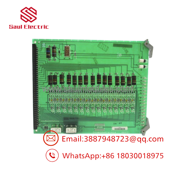
DS3800HRIA1A1A
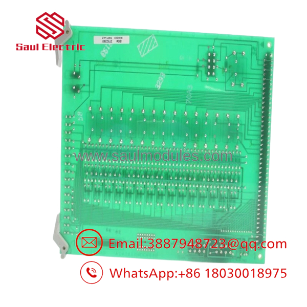
DS3800HRIA1A1A
Transparency SOP: Quality Assurance & Testing
We don’t just ship boxes; we test them on actual GE Mark IV test rigs. Here is our exact internal verification workflow before any DS3800HRIA1A1A leaves our facility:
- Inbound Visual Inspection: Check gold edge-connector fingers for wear or pitting, inspect relay casings for physical heat damage, and confirm intact OEM batch labels.
- Cold Coil Resistance Audit: Measure DC resistance across all relay coils to verify coil integrity and check for shorted turns or open circuits.
- Power-On & Backplane POST: Install the board into a live GE Mark IV test rack to confirm logic power draw and bus handshake stability.
- Relay Contact Sweep: Sequentially energize and de-energize every relay channel. Measure contact resistance across Form C contacts (NO and NC positions) under load to guarantee < 0.1 Ω contact resistance.
- LED & Status Verification: Confirm that every channel’s diagnostic LED turns on and off in exact sync with relay switching.
- ESD Packaging: Seal inside static-shielding bags with fresh desiccant packs before custom foam boxing.
The Veteran’s Tech Trap Guide (Crucial Value-Add)
⚠️ 1. Check Contact Load Ratings Before Wiring Inductive Loads!
The electromechanical relays on the DS3800HRIA1A1A are rated for control-level pilot duty. Driving heavy inductive loads like large solenoid coils or motor starters directly through these contacts without external inductive arc suppressors (flyback diodes or RC snubbers) will pit the relay contacts rapidly. If you notice contacts welding shut, install an RC snubber across the field load!
❗ 2. Watch Out for Backplane Pin Damage During Insertion
Legacy Mark IV racks use edge card sockets that can wear over time. When installing the HRIA card, line up the card guides carefully. Apply firm, steady, even pressure using both red nylon ejector clips at the same time. Never force the card at an angle, or you risk bending backplane connector pins.
⚠️ 3. De-energize Field Power Before Swapping!
While the backplane logic runs on low voltage (+5V/+15V DC), the field contacts wired to the front terminal blocks often carry 120 VAC or 125 VDC pilot power from external plant breakers. Always isolate field contact power before pulling or plugging the board to prevent accidental short circuits or arc flashes.
Frequently Asked Questions (FAQ for Conversion)
A: No. Pulling a relay interface board while the Mark IV rack is energized will open active trip and interlock contacts, causing an immediate safety trip or triggering a major fault lockout. Always perform a complete lockout/tagout (LOTO) on both rack logic and field contact supplies before replacing this board.
Q: What does the “1A1A” suffix mean?
A: In GE Mark IV part numbers, 1A1A represents the exact engineering revision level. The first 1A designates the group artwork and trace layout, while the second 1A indicates the specific installed component bill of materials (BOM) revision.
Q: How do I know if an individual relay channel has failed?
A: Check the onboard diagnostic LEDs first. If an LED lights up but the connected field device fails to actuate, measure the contact resistance across the corresponding terminal pins. High resistance (> 2 Ω) or an open circuit while the LED is lit indicates pitted or worn relay contacts.
Q: Is this unit new or refurbished, and what warranty is included?
A: We supply this module as New Surplus stock (unused factory original surplus). Every unit includes our full 12-month operational replacement warranty.
Q: Why buy surplus instead of ordering directly through GE OEM networks?
A: Legacy Mark IV series components have been long discontinued by the original manufacturer. Sourcing New Surplus from our stock avoids multi-month factory lead times, eliminates exorbitant rush fees, and provides immediate drop-in replacements for operating power plants.



 Start Chat


