





Description
Key Technical Specifications
| Parameter | Value |
|---|---|
| Bus Architecture | VMEbus Standard compliant (VME64, A32/D32 bridging) |
| Bridging Controller | UNIVERSE CA91C142 VME-to-PCI Bridge Silicon |
| Mezzanine Expansion | 2 x Single-width (or 1 x Double-width) PMC slots (IEEE P1386) |
| Communication Layer | Supports transparent bidirectional data transmission over specified carriers |
| Network Interface | 10/100Base-T Ethernet RJ45 port for control network bridging |
| System Compatibility | GE Mark VIe turbine control and EX2100 excitation frameworks |
| Power Consumption | Derived from VME backplane (+5 V DC, ±12 V DC rails) |
| Operating Temperature | −20 to +60 °C (−4 °F to 140 °F) industrial-grade environment |
Product Introduction
The GE EVPBDP0001 (often integrated or sub-assembled under the designation EVPBDP032) is a specialized VMEbus-based Communication and Controller Module developed for high-tier GE turbine and excitation control systems. Operating primarily within Mark VIe gas turbine networks or EX2100 excitation system panels, this card serves as a high-throughput, transparent communication link bridging real-time processing cores to local distribution systems.
Fengyun Automation
Engineers implement the EVPBDP0001 because it leverages the robust TMR (Triple Modular Redundant) architecture required for heavy utility generation infrastructure. Utilizing an integrated Tundra Universe chip to bridge VME and PCI operations, it allows plants to easily install up to two PMC mezzanine modules, expanding physical I/O or localized serial network structures without demanding a total system rebuild or causing high backplane latency.
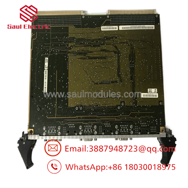
- EVPBDP0001 EVPBDP032
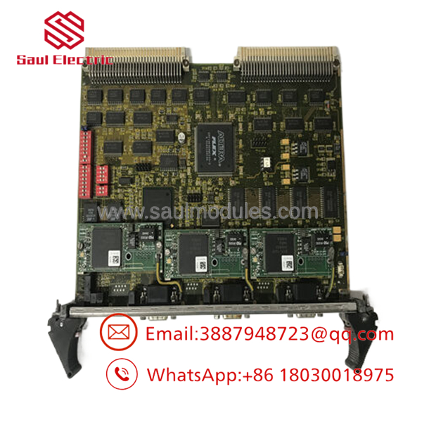
- EVPBDP0001 EVPBDP032
Installation & Configuration Guide
Stage 1: Pre-Installation Preparation (Estimated Time: 20 minutes)
- ⚠️ Safety First: The VME control rack dictates live turbine synchronization parameters or generator magnetic field strengths. Extracting a main bus module while live will instantly freeze communication, trip the generation unit, and cause catastrophic system instability. Power down the target VME rack assembly entirely. Implement formal lockout/tagout procedures at the power distribution breakers.
- Tools Required: Grounded static-dissipative ESD wrist strap, fine non-magnetic Phillips screwdriver, flat face plate lever tools, and a computer with GE ControlST / ToolboxST software.
- Data Backup: Connect your engineering workstation to the master terminal segment before cutting power. Perform a total backup upload of all running logical network topologies, card address configurations, and device maps.
Stage 2: Removing the Old Module (Estimated Time: 10 minutes)
- Affix your ESD wrist strap to a structural grounding rail inside the control cabinet.
- Disconnect the RJ45 network lines or specialized PMC communication leads routed to the card’s front plate. Clearly tag every cable destination.
- Loosen the upper and lower faceplate retaining screws that lock the module frame to the rack assembly bars.
- Flip the card injector/ejector levers outward evenly. This motion safely pulls the dual high-density VME plug matrices free from the backplane array.
- Slide the board out along the rack’s guide tracks and lay it on an approved anti-static work mat.
Stage 3: Installing the New Module (Estimated Time: 15 minutes)
- Maintain strict ESD safety protocols. Unpack the new surplus EVPBDP0001 / EVPBDP032 module.
- Transfer PMC Modules (If Required): If the new board does not include pre-installed mezzanine cards, carefully unscrew and move the physical PMC adapter boards from the old card to the new carrier. Ensure the internal multi-pin headers line up precisely and press down firmly. Secure the underside stand-off screws.
- Align the long horizontal edges of the EVPBDP0001 PCB with the plastic slot guides of the vacant rack destination.
- Push the board smoothly into the slot. Once the face levers meet the outer metal lip, squeeze the handles inward to securely set the multi-pin array into the VME backplane pins.
- Tighten the faceplate screws down to maintain shielding ground paths, then insert the network communication wires.
- Self-Checklist:
- [ ] PMC mezzanine cards seated flush and secured with physical anchoring screws.
- [ ] Ejector tabs driven firmly inward; faceplate flush with adjacent cards.
- [ ] All field network lines matched exactly to their pre-removal routing labels.
Stage 4: Power-On & Testing (Estimated Time: 20 minutes)
- Re-energize the VME chassis power rails via the master distribution breaker.
- Check the initial diagnostic light behavior on the module plate. The OK or RUN indicator should change to solid green following basic boot tests.
- Open your ToolboxST application program. Run a complete device diagnostic scan across the VME bus rack.
- Verify that the hardware configuration interface recognizes the new board assembly and any attached PMC sub-nodes without triggering protocol errors or hardware address faults.
- ⚠️ Troubleshooting Note: If the software shows a bus configuration error or fails to find the card, turn off the system power. Pull out the module and check the pins on the rear connectors. A tiny alignment error during step 4 can bend a fine backplane pin, cutting off data pathways.
Frequently Asked Questions (FAQ)
What is the relationship between model numbers and EVPBDP032?
In GE’s industrial component labeling convention, these numbers frequently designate different levels of the same physical hardware build. is typically the base order model number or tracking ID for the fully compiled circuit assembly board, whereas EVPBDP032 represents the physical printed circuit board layout matrix or a specific component revision configuration stamped directly into the green substrate during factory manufacture. They describe the exact same physical module asset.
Does the board support live hot-swapping inside a Mark VIe or EX2100 rack?
No. Standard VME64 bus configurations do not support live hot-swapping for primary carrier modules. Extracting the card while the backplane power is active causes immediate signal lines to spark and bridge data rails. This can ruin the on-chip UNIVERSE bus logic, disrupt the processing cycles of all neighboring cards, and trigger a complete emergency control shutdown across the entire turbine network.
What are the PMC expansion locations on this card used for?
The two PMC (PCI Mezzanine Card) locations allow the board to adapt to various field applications. Because the base board provides generic VME-to-PCI bus bridging, it cannot handle custom field lines out of the box. By mounting targeted PMC daughtercards onto these spaces, you can add features like specialized fiber transceivers, localized high-speed serial networks, or custom communication modems, keeping the main VME layout clean and compact.
Fengyun Automation
How do I address a persistent “VME Bus Timeout” error after installing the unit?
A bus timeout fault generally indicates an addressing conflict or an unconfigured memory offset map. If the replacement module’s internal address selections do not align with what the main rack controller expects, data packets will drop out. Access your project configuration settings in ToolboxST and verify that the base slot address and VME memory range settings assigned to this specific slot index perfectly match your plant’s original hardware blueprint documentation.
Why is this equipment sometimes listed under alternate manufacturer classifications?
GE built these specialized VME platforms to work across their major power generation divisions, so you will find them filed under GE Gas Turbine Systems, GE Multilin, or GE Hydro/Excitation networks. No matter which specific catalog listing you encounter, as long as the base manufacturer tracking model identifies as / , the component is physically and electrically identical, providing the exact same data translation features across all systems.



 Start Chat


