





Description
Product Introduction
The GE Fanuc IC670ALG240 is an 8-channel analog current input module designed for GE’s modular Field Control distributed I/O system. Created to bridge field instrumentation directly to central controllers (such as Series 90-30, Series 90-70, or Genius networks via Field Control Bus Headers), this compact module accepts standard process current signals like 4-20mA and 0-20mA from transmitters across eight individual channels.
By mounting directly onto a Field Control Terminal Block (such as the IC670TBX001), the IC670ALG240 performs analog-to-digital conversions close to field sensors. Its onboard A/D converter processes current inputs with 12-bit accuracy, allowing central PLC logic to monitor process variables like pressure, temperature, level, and flow with minimal signal noise degradation.
Key Technical Specifications
| Parameter | Specification |
| Manufacturer | GE Fanuc / Emerson |
| Part Number | IC670ALG240 |
| System Compatibility | GE Field Control Station (Bus Header required) |
| Associated Terminal Base | IC670TBX001 / IC670CHS001 |
| Input Signal Types | 0 to 20 mA, 4 to 20 mA |
| Number of Channels | 8 single-ended current channels |
| Resolution | 12 bits (1 part in 4096) |
| Input Impedance | 250 ohms (internal precision sense resistor) |
| Bus Power Consumption | 5 VDC @ 50 mA (from Field Control bus) |
| Isolated User Power | 24 VDC nominal (20 to 30 VDC required for loop power) |
| Update Rate | 2.0 ms total for all 8 channels |
Application Scenarios & The “Trench” Experience
It’s 11:30 PM at a municipal wastewater pumping facility. A remote Field Control drop handling wet-well levels and pump discharge pressures loses telemetry on four channels simultaneously. The central PLC throws an analog range error, causing effluent pumps to run continuously on manual override. The issue stems from an internal A/D converter failure on the old IC670ALG240 card after years of high-humidity panel operation.
Primary Industrial Applications
- Water & Wastewater Treatment: Lift Station Monitoring – Reads multi-channel ultrasonic level sensors and flow transmitters.
- Chemical Skid Automation: Dosing System Control – Monitors mass flow meters and inline pH/conductivity transmitters.
- Oil & Gas Gathering Systems: Wellhead Pressure Monitoring – Tracks suction and discharge pressures across distributed compression skids.
- Building Energy Management: Chilled Water Systems – Gathers differential pressure and flow data across HVAC cooling loops.
Field Case Study
A chemical processing plant in Texas experienced a sudden channel drop on its tank farm monitoring rack. Rather than upgrading the entire Field Control drop—which would require replacing the Bus Header, re-pulling field cables, and updating PLC software—the maintenance supervisor replaced the faulty card with a pre-tested surplus IC670ALG240. The swap was completed on the live terminal base in under 10 minutes, restoring real-time tank level readings without stopping plant production.
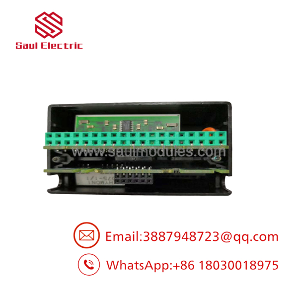
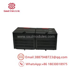
IC670ALG240
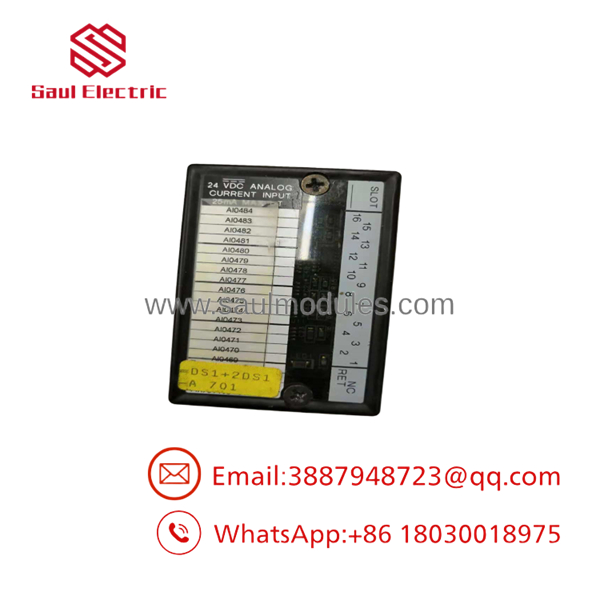
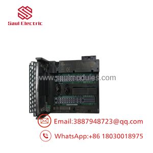
IC670ALG240
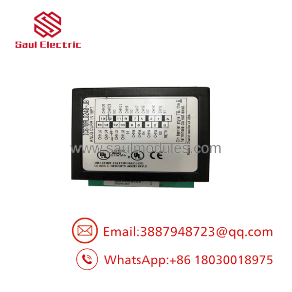
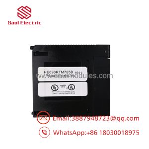
IC670ALG240
Transparency SOP: Quality Assurance & Testing
Every IC670ALG240 card is tested on live Field Control test benches:
- Connector & Housing Inspection: Check of edge pins, casing snap latches, and internal PCB components for corrosion, thermal discoloration, or mechanical damage.
- Base Engagement Verification: Plugging the module onto an active terminal base (IC670TBX001) connected to a Field Control Bus Header (e.g., IC670GBI002 / IC670PBI001) to confirm backplane communications.
- 8-Channel Signal Precision Audit: Injecting reference 4.0mA, 12.0mA, and 20.0mA signals across all 8 channels simultaneously using a calibrated signal generator to verify 12-bit conversion accuracy.
- Thermal Stability Screening: Running continuous channel scans under load to ensure onboard ADC reference circuits show zero thermal drift.
- ESD Packaging & Protection: Clearing configuration registers, placing the module inside an anti-static ESD bag, and packing with custom foam cushioning.
The Veteran’s Tech Trap Guide (Crucial Value-Add)
⚠️ Trap 1: Do Not Forget External 24V Loop Power!
The draws 5V logic power from the Field Control backplane, but current loops require an external 24 VDC user power supply connected to the terminal base. If your 4-20mA transmitters read flat 0mA while the Field Control station LED indicates “OK”, check for missing 24V field power before assuming the module is dead.
❗ Trap 2: Verify Single-Ended Wiring Polarization.
The features single-ended inputs with a common return ground across channels. Connecting a 4-wire transmitter or non-isolated loop with a conflicting ground reference can create ground loops, causing offset errors or blown input sense resistors.
⚠️ Trap 3: Respect Bus Header I/O Memory Limits.
Field Control Bus Headers (such as Genius, Profibus, or DeviceNet headers) impose total I/O memory limits per remote node. Adding multiple high-density analog modules like the can quickly consume available input word allocations. Always check your node memory map in Proficy Machine Edition.
❗ Trap 4: Never Pull Module Base Terminal Block Wiring Under Load.
While Field Control allows module replacement, pulling field wiring terminals from the base card while 24V transmitter power is applied can arc across base connector pins, damaging adjacent channel input circuits.
Frequently Asked Questions (FAQ for Conversion)
Q: Can I replace the module without unwiring field cables?
A: Yes! The Field Control system separates the electronics module () from the terminal wiring base (IC670TBX001). You simply unlatch the top module and pull it straight off the base without touching any field screw terminals.
Q: What is the difference between and IC670ALG320?
A: The is an Analog Input module (reads 4-20mA signals), whereas the IC670ALG320 is an Analog Output module (drives 4-20mA signals out to field devices).
Q: Can individual channels be configured for 0-20mA instead of 4-20mA?
A: Yes. Input range selection (0-20mA or 4-20mA) and scaling parameters are configured via software settings inside the Field Control Bus Header hardware configuration tree.
Q: Why source pre-tested surplus modules over upgrading the system?
A: Upgrading a legacy Field Control drop requires migrating network interfaces, replacing field wiring bases, redrawing panel schematics, and re-writing PLC I/O maps. Dropping in a pre-tested replacement gets your system running in minutes at a fraction of the cost.
Q: What warranty comes with this module?
A: Every module includes a full 12-month functional replacement warranty. If any channel or internal component experiences failures under normal operating conditions within 365 days, we replace it immediately.

 Start Chat


