





Description
Product Introduction & Engineering Value
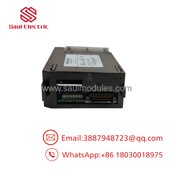
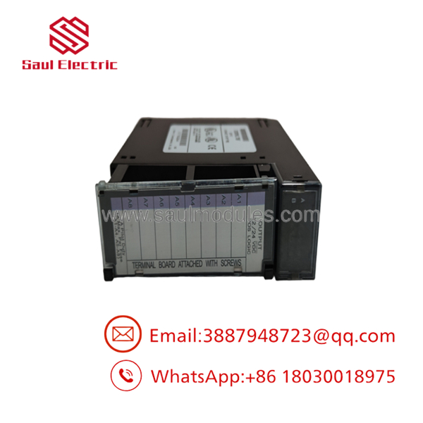
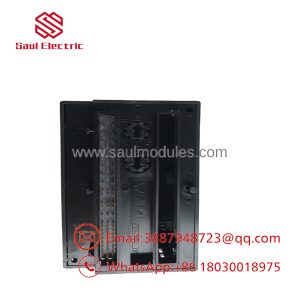
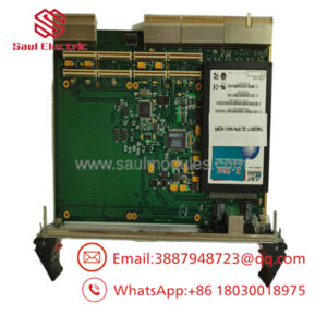
High-duty inductive loads inside a control panel will quickly cook standard 0.5A PLC output cards. The GE Fanuc IC693MDL730 is designed specifically for these high-current applications, offering 8 sourcing (positive logic) outputs capable of switching up to 2.0 Amps continuous per channel. Occupying a single slot on any Series 90-30 baseplate, it bridges control-level software commands to rugged field devices like heavy hydraulic solenoid valves, DC contactors, and warning horns without needing interposing relays.
Unlike basic solid-state switching cards, the IC693MDL730 incorporates electronic short-circuit and overcurrent protection to shield internal MOSFET switches from field wiring faults. High-speed transient suppression is built directly into each channel to absorb back-EMF voltage spikes generated when de-energizing large inductive coils. For operators managing continuous material handling or stamping equipment, stocking a tested IC693MDL730 keeps heavy control loops protected and responsive.
Technical Specifications
- Outputs per Module: 8 sourcing (positive logic) channels
- Operating Voltage Range: 12 to 24 VDC nominal (+12 to +30 VDC maximum limits)
- Output Current Rating: 2.0 Amps maximum per point at 60°C (120°F)
- Module Grouping: 8 points divided into 2 isolated groups of 4 points each (2.0A per point, 4.0A max per group/common)
- Inrush Current Capacity: 5.0 Amps maximum for 10 milliseconds
- OFF-State Leakage Current: 1.0 mA maximum per channel
- ON-State Voltage Drop: 1.2 VDC maximum at full 2.0A load
- Response Time: 0.5 ms maximum for turn-ON / 1.0 ms maximum for turn-OFF
- Isolation Rating: 1,500 VAC optical isolation between field terminals and backplane logic
- Backplane Power Draw: 55 mA maximum from the +5 VDC bus rail
- Status Indicators: 8 green point LEDs (I/O state) + 2 red FUSE/FAULT LEDs (1 per group)
Field Application & The “Trench” Experience
The Hydraulic Scrap Baler Shutdown
At a regional recycling plant, a heavy-duty hydraulic scrap baler ground to a halt during the peak afternoon shift. The main hydraulic directional control valves refused to shift, and the red fault LED on the panel’s output card turned solid red. The plant electrician discovered that an external wire harness on a 24V hydraulic solenoid valve had chafed against the structural frame, dead-shorting Channel 2 to ground.
On a standard relay card, this direct short would have welded the internal contacts shut or vaporized the circuit board traces. On the IC693MDL730, the onboard electronic protection tripped, isolating the faulted group and turning on the group’s red fault indicator to prevent further component damage. The electrician repaired the harness insulation, cleared the fault, and cycled field power. The IC693MDL730 reset its internal driver automatically, bringing the baler back into operation within 15 minutes without needing a board replacement.
Key Deployment Scenarios
- Automated Stamping Presses: Direct driving of 24V DC clutch and brake solenoids requiring fast 0.5 ms response times.
- Heavy Industrial Conveyor Skids: Switching 24 VDC motor starter coils and pneumatic diverter gate valves directly from PLC rack outputs.
- Offshore Drilling Rig Flare Stacks: Controlling high-current ignition coils and fuel shut-off valves across isolated power groups.
- IC693MDL730
Transparency SOP: QA & Testing
[1. Mechanical & Pin Inspection] ──> [2. 5V Backplane Logic Check] ──> [3. 2A Full-Load Channel Sweep] ──> [4. Overcurrent & Fault Test]
- Mechanical & Connector Integrity Inspection: We inspect the module enclosure for cracked retaining clips, check all backplane card-edge contacts for oxidation, and verify that the removable terminal block screw threads operate smoothly.
- Backplane Power Rail Benchmark: The module is seated in a Series 90-30 rack and powered at 5.0 VDC to confirm logic current draw remains well under the 55 mA maximum threshold.
- High-Current Full-Load Sweep: Using a 24 VDC power supply and calibrated electronic resistive loads, each of the 8 channels is driven at a full 2.0 Amps continuous load for two hours. Thermal imaging is used to verify stable MOSFET operating temperatures.
- Short-Circuit Protection & Fault LED Trigger: Each output group is momentarily subjected to an overcurrent fault condition to confirm that internal electronic trip circuits disengage output drivers safely and illuminate the front-panel red group fault LEDs.
The Veteran’s Tech Trap Guide (Crucial Value-Add)
⚠️ TRAP 1: Group Current Limits vs. Individual Channel Ratings Do not fall into the “math trap” on total current draw! While each individual point on the is rated for 2.0 Amps, each 4-point group is limited to 4.0 Amps total. If you turn ON all four channels in Group A simultaneously at 2.0 Amps each (8.0A total), you will overheat the common bus trace and trip the group’s internal thermal shutdown. If all 8 channels need to run high current simultaneously, split high-draw loads evenly across both groups or use separate modules.
⚠️ TRAP 2: Flyback Suppression on Highly Inductive DC Coils Although the includes built-in transient suppression diodes, switching heavy DC solenoids (over 1.5A) several times per second produces intense inductive back-EMF spikes. For ultra-high-cycle solenoid applications, always install an external flyback diode (such as a 1N4004) directly across the solenoid coil terminals in the field. This prevents high-voltage flyback noise from creeping back onto your 24V field supply rail.
PRO TIP: Resetting Electronic Group Faults When the red group fault LED illuminates, the affected group latches OFF for safety. Simply fixing the field short circuit will not clear the fault state automatically. You must cycle the 24 VDC field power supply connected to that group’s common terminal (or toggle the output bit off and on in ladder logic) to reset the internal electronic circuit breaker.
Dynamic FAQ
Q: Can I mix 12 VDC and 24 VDC power sources on the same card? A: Yes! The 8 output channels are split into two completely isolated groups of 4 points (Group A: points 1–4; Group B: points 5–8). You can run a 12 VDC supply on Group A’s common and a 24 VDC supply on Group B’s common without cross-talk or interference.
Q: How is the different from the IC693MDL740? A: The is an 8-point, 2.0A per channel high-current output module. The IC693MDL740 is a 16-point, 0.5A per channel standard-current output module. Choose the MDL730 when driving heavy solenoids and contactor coils directly.
Q: Does this module require an external field power supply to operate? A: Yes. The backplane bus only powers the internal optical isolation and logic circuits (55 mA). An external 12 VDC or 24 VDC field power supply must be connected to the group common terminals on the front terminal block to drive connected field loads.
Q: Are the internal group fuses user-replaceable? A: The uses solid-state electronic overcurrent protection rather than traditional glass filament fuses. When a short circuit occurs, the electronic circuit trips automatically. Once the short is removed and field power is cycled, the module resets without needing physical fuse replacements.
Q: What warranty coverage applies to your surplus stock? A: Every module—whether certified new surplus or fully reconditioned—undergoes 2.0A full-load stress testing and comes backed by our 12-month full-replacement warranty in anti-static protective packaging.

 Start Chat


