



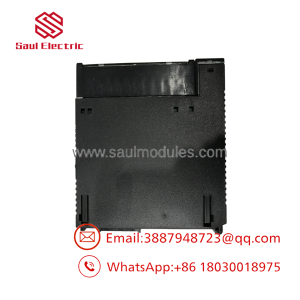
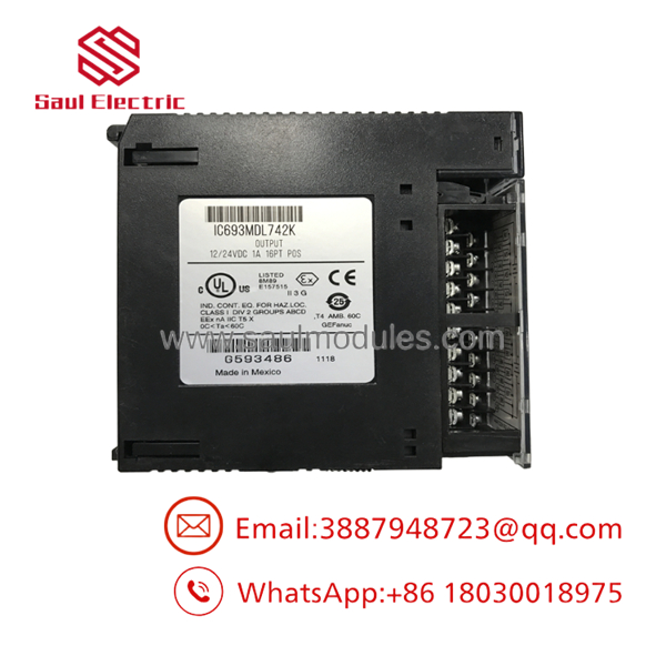


Description
| Parameter | Specification Details |
| Model | IC693MDL742 (Replaces IC693MDL742A through K) |
| Brand | GE Fanuc / Emerson Automation |
| Series | Series 90-30 Programmable Controller |
| Product Type | 16-Point 12/24 VDC 0.5A Positive Logic (Sourcing) Output Module |
| Core Function | Drives medium-duty DC field loads such as indicator lights, small solenoids, and interposing relays directly from Series 90-30 backplane logic commands. |
| Key Specifications | 12 to 24 VDC nominal operating range (+12V to +30V DC limits), 0.5A max per point (2.0A max per common group), electronic short-circuit protection. |
Product Introduction & Engineering Value
When high density and solid-state reliability matter, relay output cards can become a maintenance bottleneck due to mechanical contact wear. The GE Fanuc IC693MDL742 addresses this challenge by providing 16 sourcing (positive logic) solid-state outputs on a single Series 90-30 card. Operating across a 12 to 24 VDC range, it delivers fast, chatter-free switching for pilot lights, control relays, and small pneumatic valves without the finite lifespan of mechanical relays.
Engineered to handle high-duty automation cycles, the IC693MDL742 features internal electronic overcurrent and short-circuit protection to protect its output drivers from field wiring mishaps. The 16 points are divided into two isolated 8-point groups, allowing plant engineers to run separate power sources or voltage levels on the same module. For facilities relying on Series 90-30 control racks, maintaining spare IC693MDL742 cards ensures rapid recovery when field channels are damaged by external electrical surges.
Technical Specifications
- Outputs per Module: 16 sourcing (positive logic) transistor channels
- Operating Voltage Range: 12 to 24 VDC nominal (+12 to +30 VDC maximum limits)
- Output Current Rating: 0.5 Amps maximum per point at 60°C (120°F)
- Module Grouping: 16 points divided into 2 isolated groups of 8 points each (0.5A per point, 2.0A max per group/common)
- Inrush Current Capacity: 2.0 Amps maximum for 10 milliseconds
- OFF-State Leakage Current: 1.0 mA maximum per channel
- ON-State Voltage Drop: 1.2 VDC maximum at full 0.5A load
- Response Time: 0.5 ms maximum for turn-ON / 1.0 ms maximum for turn-OFF
- Isolation Rating: 1,500 VAC optical isolation between field terminals and backplane logic
- Backplane Power Draw: 110 mA maximum from the +5 VDC bus rail
- Status Indicators: 16 green point LEDs (I/O state) + 2 red FUSE/FAULT LEDs (1 per group)
Field Application & The “Trench” Experience
The Bottling Plant Labeler Jam
At a regional beverage bottling plant, an automated labeling carousel stopped unexpectedly during a high-speed production run. The diagnostic table in Proficy Machine Edition pointed to Slot 6 on the main Series 90-30 rack, where a red fault LED was glowing bright red on an output module. An electrician traced the issue to a shorted pneumatic actuator coil on the bottle-reject arm, which had pulled excessive current on Point 3.
Because the installed IC693MDL742 module incorporates electronic short-circuit protection, the internal driver shut down Channel 3 safely before board traces or backplane optocouplers could burn out. The technician replaced the shorted solenoid coil, cleared the jam, and cycled 24 VDC power to the card’s group common. The IC693MDL742 reset its internal driver instantly, bringing the labeling line back into service in under 20 minutes without requiring a card swap.
Core Application Environments
- High-Speed Conveyor Diverters: Driving 24 VDC pneumatic directional valves with fast 0.5 ms switching speeds.
- Automated Assembly Workcells: Actuating arrays of 24V indicator lamps, stack lights, and piezo alarms across dual power groups.
- Chemical Dosing Control: Interfacing intermediate control relays for variable-speed chemical feed pumps without contact arc degradation.
Transparency SOP: QA & Testing
[1. Structural & Pin Inspection] ──> [2. 5V Logic Current Test] ──> [3. 0.5A Full-Load Channel Sweep] ──> [4. Electronic Fault Tripping]
- Mechanical & Physical Inspection: We check the module plastic frame for broken retention clips, inspect backplane gold-finger contacts for oxidation, and verify that terminal block screws turn freely.
- Backplane Logic Verification: The module is installed in a Series 90-30 rack and powered at 5.0 VDC to confirm backplane logic current draw remains below the 110 mA maximum threshold.
- 0.5A Load Channel Sweep: Using a 24 VDC power supply and calibrated electronic loads, each of the 16 channels is driven at 0.5 Amps continuous load. Thermal imaging is used to verify uniform heat dissipation across both 8-point output arrays.
- Short-Circuit Protection Test: Each group is subjected to a momentary overcurrent fault condition to confirm that internal electronic trip circuits disengage output drivers safely and illuminate the front-panel red group fault LEDs.
The Veteran’s Tech Trap Guide (Crucial Value-Add)
⚠️ TRAP 1: The 2.0A Group Limit vs. 0.5A Point Rating Pay close attention to your total current math! Although each individual point on the can switch up to 0.5 Amps, each 8-point group is strictly capped at 2.0 Amps total. If you turn ON all 8 channels in Group A simultaneously at 0.5 Amps each (4.0A total), you will overload the group bus and trigger an electronic thermal shutdown. If all 16 channels must run at full load simultaneously, consider splitting high-draw loads across multiple modules.
⚠️ TRAP 2: Sourcing (Positive Logic) vs. Sinking (Negative Logic) The is a sourcing (positive logic) output card, meaning it supplies +12/24 VDC power out of its terminal points to your field load (which must be connected to DC common). If your field devices are wired to accept a sinking output (switched ground), this card will not operate them. For sinking DC output applications, select the
IC693MDL741orIC693MDL740module instead.
PRO TIP: Clearing Red Group Fault LEDs When a short circuit occurs on a channel, the corresponding red group fault LED illuminates and latches the entire 8-point group OFF for safety. Fixing the field wiring short will not automatically restore output operation. You must cycle the external 24 VDC field power supply connected to that group’s common terminal (or toggle the output bit off and on in software) to reset the internal electronic circuit breaker.
Dynamic FAQ
Q: What is the primary difference between the and the IC693MDL740? A: Both are 16-point 12/24 VDC output cards. However, the is a sourcing (positive logic) module that switches positive voltage to loads, whereas the IC693MDL740 is a sinking (negative logic) module that switches DC ground to loads.
Q: Can I run 12 VDC on Group A and 24 VDC on Group B of the same card? A: Yes! The 16 channels are divided into two completely isolated 8-point groups (Group A: points 1–8; Group B: points 9–16). You can supply 12 VDC to Group A’s common and 24 VDC to Group B’s common without interference.
Q: Are the group fuses on the user-replaceable? A: No. The uses solid-state electronic overcurrent protection rather than physical glass fuses. When a short circuit occurs, the internal circuit trips electronically and can be reset by cycling field power once the short is removed.
Q: Does this module draw its field load power from the PLC backplane? A: No. The backplane only supplies power (110 mA max) for internal optocouplers and logic processing. An external 12 VDC or 24 VDC field power supply must be connected to the group common terminals on the front terminal block to power connected field loads.
Q: What warranty coverage is included with your surplus inventory? A: Every module—whether certified new surplus or fully reconditioned—undergoes full 16-channel load testing and includes our standard 12-month full-replacement warranty in anti-static ESD packaging.

 Start Chat


