





Description
Product Introduction & Engineering Value
Designing fault-tolerant control architectures usually means fighting cabinet space constraints while maintaining physical isolation between redundant controllers. The GE Fanuc IC697CHS770 Dual Redundant Rack solves this by splitting a single 19-inch rear-mount chassis into two completely independent 6-slot backplane sections.
Each side features its own dedicated power supply connector, allowing primary and backup controllers (or IC687/IC697 redundancy modules) to operate in a single mechanical footprint without sharing a common VME backplane bus. Because the backplane features 0.8-inch VME connector spacing, it seamlessly accepts standard double-width 1.6-inch IC697 PLC modules alongside specialized 3rd-party VME cards.
Technical Specifications
- Mounting Type: Panel / Rear Wall Mount (fits standard 10-inch deep enclosures)
- Total Backplane Slots: 12 VME physical slots (6 slots per backplane section)
- Module Capacity: Up to 6 standard IC697 PLC modules (occupying 2 slots each) or 10 single-width VME modules total
- Power Supply Capacity: 2 Dedicated Power Supply Bays (leftmost and rightmost positions)
- Slot Spacing: 0.8 inches (20.3 mm) VME standard pitch
- Slot Addressing: Automatic slot-sensing via backplane jumpers (no DIP switches required on I/O)
- Physical Dimensions: 11.15″ H x 19.00″ W x 7.25″ D (283mm x 483mm x 184mm)
- Weight: ~20.0 lbs (9.07 kg) unpopulated
- Auxiliary Power Link: Supports Power Supply Extension Cable Kit (IC697CBL700) to share power across sections if needed
- Thermal Management: Natural convection; optional Rack Fan Assemblies (IC697ACC721 / IC697ACC724) available for high-wattage deployments.
Field Application & The “Trench” Experience
During an emergency overhaul at a petrochemical refining plant, an aging dual-chassis Hot Standby PLC setup suffered physical backplane damage after an electrical arc event on the primary power bus. The plant ran dual IC697CGR772 redundant CPUs tied to high-density analog monitoring loops.
Replacing two burnt individual 5-slot racks with a single IC697CHS770 chassis allowed maintenance engineers to consolidate primary CPU A and backup CPU B into one rigid panel space. Tying each backplane section to separate isolated power feeds (IC697PWR711) restored bumpless CPU failover in under two hours without altering the enclosure footprint or rewiring field swings.
Target Installation Scenarios:
- Hot Standby Process Control: Mounting Primary and Secondary Series 90-70 CPUs in isolated backplane zones with an IC687 Redundancy Communications Module.
- Hybrid VME Data Acquisition: Combining Series 90-70 CPU control logic with 0.8-inch wide 3rd-party VME signal processing boards in a unified chassis.
- High-Availability Turbine Trips: Structuring dual-redundant voting circuits where complete electrical isolation between controller channels is mandated.
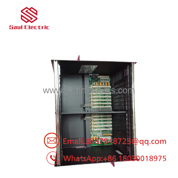
- IC697CHS770
Transparency SOP: QA & Testing
Every IC697CHS770 chassis coming through our reconditioning process undergoes structural and electrical validation on our Series 90-70 test stand:
- Backplane & Pin Alignment Inspection: Every DIN/VME backplane connector pin is checked under optical magnification for bending, oxidation, or cracked solder joints.
- Dual-Zone Power Isolation Test: Both left and right power supply connectors are energized independently to confirm zero voltage leakage between Section A and Section B backplanes.
- Interrupt Continuity Check: Test CPU and I/O cards are seated sequentially across all 12 slot positions to verify unbroken slot-sensing and interrupt pass-through logic.
- Full-Load Stress Test: Populated with twin CPUs and high-current discrete output cards, running a 100% duty cycle test for 12 hours under thermal load.
The Veteran’s Tech Trap Guide
⚠️ BLANK SLOT INTERRUPT JUMPERS: If you leave empty module slots between populated cards on either section of the IC697CHS770 backplane, you must install Blank Slot Interrupt Jumpers (IC697ACC722). Leaving an unpopulated slot open breaks the VME bus daisy-chained interrupt line, causing downstream modules to fail system initialization!
⚠️ 1.6-INCH VS 0.8-INCH SPACING: Remember that standard IC697 PLC modules are 1.6 inches wide and take up two backplane slot connectors (0.8″ each). Do not attempt to force 3rd-party 0.8″ single-width cards into a slot designated for a double-width module without reviewing GFK-1447 VME alignment rules.
PRO TIP: When setting up a dual-redundant configuration, assign distinct rack addresses using the backplane jumpers located directly behind the power supply bays. Always ensure the primary rack section is recognized as Rack 0 by the main CPU software configuration.
Dynamic FAQ
Q: Can I run a single Power Supply to run BOTH sections of the IC697CHS770 rack?
A: Yes, but only if you use the optional Power Supply Extension Cable Kit (IC697CBL700). Otherwise, each 6-slot section requires its own dedicated IC697 power supply module inserted into its respective power bay.
Q: What is the difference between the and the IC697CHS771?
A: The is designed for rear panel mounting inside an enclosure, whereas the IC697CHS771 is configured with front-mounting flanges for direct installation into standard 19-inch equipment racks.
Q: Do I need external cooling fans for this rack?
A: For standard PLC modules operating within ambient temperature specs, natural convection is sufficient. However, if you are installing high-wattage 3rd-party VME cards or operating in ambient temperatures above 45°C, installing a Rack Fan Assembly (IC697ACC721 or IC697ACC724) is highly recommended.
Q: What condition is your stock in, and does it come with a warranty?
A: We offer both New Surplus and fully reconditioned racks. Every chassis is cleaned, backplane-tested, and shipped with our standard 2-year full replacement warranty.
Q: How many standard IC697 PLC modules can fit in this chassis?
A: The rack supports up to 6 standard double-width PLC modules (3 per side) alongside two power supply modules.

 Start Chat


