





Description
Product Introduction & Engineering Value
Attempting to coast down high-inertia gas turbine rotors without controlled electrical braking subjects bearings to prolonged turning-gear transition stress and drags out outage timelines. The GE GESSBS-6AH256 Static Synchronous Brake Board coordinates the precise sequence needed to convert a turbine generator into an electrical brake during shutdown.
By controlling the firing angles of the load commutated inverter (LCI) bridge and regulating DC current injection into the stator, this board absorbs rotational kinetic energy safely through the station resistor banks. It provides tight timing handshakes with the primary drive controller while isolating sensitive processing logic from high-voltage DC bus transients.
Technical Specifications
- Board Type: Static Synchronous Braking Control / Interface Module
- Application System: LS2100 Static Starter / GE Innovation Series Drives
- Signal Inputs: Phase voltage feedback, DC bus link current monitoring, external permissive interlocks
- Control Outputs: SCR gate pulse firing commands to power bridge driver cards
- Circuit Architecture: Multi-layer FR-4 glass-epoxy substrate with isolated analog and digital signal routing
- Form Factor: Standard GE drive rack PCB with card-edge multi-pin headers
- Operating Temperature Range: -30°C to +65°C (-22°F to +149°F)
- Environmental Protection: Conformal coated for industrial cabinet deployment
Field Application & The “Trench” Experience
The Trench Story: During a fast-turnaround trip sequence on a Frame 7FA gas turbine, the static starter system threw a “Braking Timeout” fault, leaving the rotor coasting freely for over 45 minutes. Signal tracing at the drive cabinet showed that the gating enable signal from the original braking board was dropping out intermittently due to thermal drift in its onboard comparator circuit. Installing a tested GESSBS-6AH256 board restored crisp gate command timing, brought the turbine rotor from 3,600 RPM to turning-gear speed in under 12 minutes, and allowed the plant to meet its dispatch window.
Niche Application Scenarios
- Combustion Turbine Emergency Deceleration: Manages rapid, controlled electrical deceleration during emergency shut-downs to minimize mechanical bearing wear.
- LCI Static Starter Cooldown Ramping: Controls low-speed braking torque to transition the generator onto turning gear smoothly during routine shutdowns.
- Hydro-Generator Synchronous Braking: Absorbs mechanical energy on high-inertia hydroelectric units to prevent overspeed hunting during de-watering routines.
Transparency SOP: QA & Testing
- Visual & Solder Joint Audit: High-magnification inspection of all surface-mount passive components, card-edge fingers, and pin headers for micro-cracks or heat discoloration.
- Dielectric Insulation Resistance Test: High-potential (Hi-Pot) verification between high-voltage sensing inputs and low-voltage digital signal buses.
- Bench Simulator Sequence Test: Insertion into a simulated LS2100 drive rack to verify gate pulse timing, enable logic handshakes, and fault relay trip response.
- Thermal Stability Cycling: Operating the board under simulated signal load in a climate chamber to ensure zero component value drift at elevated temperatures.
- ESD Cleaning & Packaging: Ultrasonic pin cleaning followed by vacuum packaging in static-shielded anti-static bags with fresh desiccant.
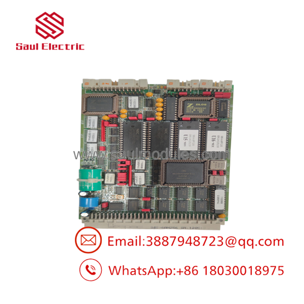
- GESSBS-6AH256
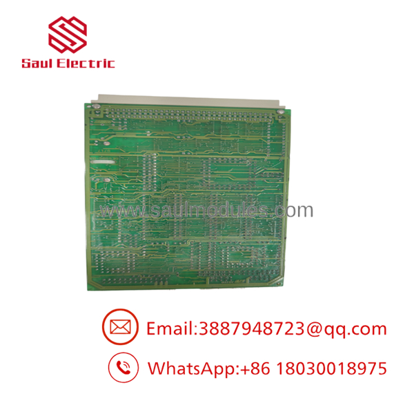
- GESSBS-6AH256
The Veteran’s Tech Trap Guide
- ⚠️ High Residual Voltage Hazard: The GESSBS-6AH256 interface routes directly into high-energy DC link and field circuits. Always verify that the main LCI isolation breakers are open and that the DC bus link capacitors are fully discharged before pulling or landing wires on this board!
- PRO TIP: Verify Card Guide Slot Alignment: When sliding the GESSBS-6AH256 into the drive rack, ensure both the top and bottom edge card rails are squarely seated before pushing. Misaligned insertion can bend backplane header pins on the rear chassis connector, shorting out adjacent control channels.
- ⚠️ Do Not Swap Under Power: This card does not support hot-swapping. Removing or inserting the while 24 VDC control power is active will send spurious firing pulses to the LCI bridge, potentially causing an arm-over or shorting the SCR bridge modules.
Dynamic FAQ
Q: What is the primary role of the in an LS2100 Static Starter?
A: It manages the static electrical braking cycle during turbine shutdown, firing the LCI bridge to dump the rotor’s mechanical kinetic energy into electrical load banks.
Q: Does this board require software flashing or firmware loading upon installation?
A: No. The operates as a hardware interface and logic board. System-level parameters are managed by the main drive controller (e.g., DSPC card), so no direct software flashing on this board is required.
Q: What are the warning signs that a braking control board is degrading?
A: Common symptoms include extended coast-down times, erratic DC link current faults during braking deceleration, or “Braking Permissive Lost” alarms on the operator terminal.
Q: How are your surplus boards preserved prior to shipment?
A: Units are stored in climate-controlled environments inside sealed anti-static bags with desiccant packs to prevent trace oxidation and component moisture absorption.
Q: What warranty coverage is included with this module?
A: All units ship with a standard 12-month full-replacement warranty covering electronic functionality, gate pulse drive output, and signal accuracy.




 Start Chat


