





Description
Key Technical Specifications
| Parameter | Value |
|---|---|
| Manufacturer | GE Fanuc |
| Model Number | HE693STG884D |
| Product Type | Analog Strain Gage Input Module |
| PLC Platform | GE Series 90-30 |
| Number of Channels | 8 |
| Supported Sensors | Bridged strain gages and load cells |
| Selectable Input Ranges | ±25 mV, ±50 mV, ±100 mV |
| Resolution | 0.8 µV, 1.6 µV, 3.2 µV (depending on range) |
| Accuracy | ±0.3% |
| A/D Conversion | Integrating, 35 channels/second |
| Input Impedance | >1,000 MΩ |
| Excitation Monitoring | 10 V DC |
| Maximum Safe Input Voltage | ±35 V AC/DC |
| Operating Temperature | 0 °C to +60 °C |
| Power Consumption | 60 mA @ 5 V DC, 30 mA @ 24 V DC relay |
Product Introduction
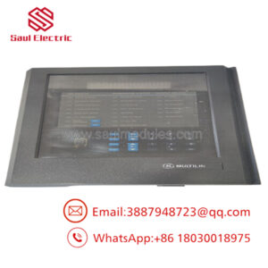
The GE HE693STG884D is an 8-channel analog strain gage input module for the GE Fanuc Series 90-30 PLC. It allows bridged strain gages and load cells to connect directly to the PLC without requiring external transmitters or signal conditioners. All analog processing is performed internally, and measured values are transferred directly into the PLC analog input table.
In weighing systems, material handling equipment, hydraulic presses, and force measurement applications, this module simplifies installation while providing high-resolution millivolt measurement. Before replacing the module, verify the PLC rack compatibility, Logicmaster configuration, and channel range settings to avoid unnecessary commissioning delays.
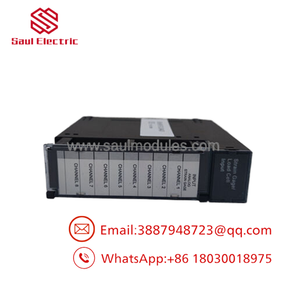
- HE693STG884D
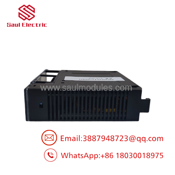
- HE693STG884D
Troubleshooting Quick Reference
| Symptom | Possible Cause | Relevance to this Part | Quick Check Method | Recommendation |
|---|---|---|---|---|
| All channels read zero | Load cell excitation missing | ❌ Low | Measure the 10 V excitation output | Verify field wiring before replacing the module |
| One channel unstable | Damaged load cell cable | ❌ Low | Measure bridge resistance and inspect shielding | Repair field wiring first |
| Constant over-range reading | Incorrect input range configuration | ✅ High | Verify Logicmaster channel configuration | Select the correct ±25/±50/±100 mV range |
| PLC reports module fault | Internal module diagnostics failed | ✅ High | Review PLC fault table and module status LEDs | Replace the module if diagnostics confirm failure |
| Noisy measurement | Ground loop or poor shielding | ❌ Low | Inspect cable shield termination | Use single-point shield grounding |
| Measurement drift | Load cell or excitation variation | ✅ Medium | Compare excitation voltage with specification | Verify sensor before replacing the module |
| No module detected | Rack connector issue | ✅ Medium | Reseat the module and inspect the backplane connector | Clean contacts and retest |
Technical Note: This module has a strong reliability record. In practice, failed load cells, damaged field wiring, incorrect scaling, or shielding problems account for far more service calls than actual module failures. Review PLC diagnostics before replacing hardware.
Frequently Asked Questions (FAQ)
Q1. What is the HE693STG884D used for?
It is designed to connect bridged strain gages and load cells directly to a GE Series 90-30 PLC. External transmitters are generally not required because the module performs signal conditioning internally.
Q2. How many sensors can the module support?
The module provides eight independent input channels, allowing multiple load cells or strain gage sensors to be monitored simultaneously.
Q3. Can I hot-swap the module?
No.
The Series 90-30 platform was not designed for routine hot swapping. Shut down the PLC rack and follow your plant’s lockout/tagout procedure before removing or installing the module.
Q4. Why are there multiple selectable input ranges?
Different load cells produce different millivolt outputs. Selecting the correct ±25 mV, ±50 mV, or ±100 mV range provides the highest measurement resolution for your application.
Q5. Why is New Surplus inventory less expensive than factory inventory?
Most New Surplus modules originate from canceled automation projects, OEM spare inventories, or unused maintenance stock. They have not been placed into production service but are no longer manufactured by the OEM.
Q6. What should I verify before ordering?
Verify:
- Exact model number (HE693STG884D)
- PLC Series 90-30 compatibility
- Logicmaster configuration
- Input range requirements
- Load cell wiring
- Terminal block condition
A few minutes of verification can prevent unnecessary troubleshooting after installation.
Q7. What warranty is typically available?
Most industrial automation suppliers provide a 12-month warranty on verified New Surplus or professionally tested modules. Request the functional test report and inspection records before shipment.
Quality Inspection & Testing SOP
1. Inbound Inspection & Traceability
- Verify GE Fanuc labels, serial numbers, and model identification.
- Inspect the PCB and housing for corrosion, cracked components, bent connector pins, or evidence of previous repair.
- Confirm the terminal block is complete and undamaged.
- Record serial numbers for traceability.
2. Live Functional Testing
- Install the module in an in-house GE Series 90-30 PLC test rack.
- Verify normal startup and module recognition.
- Connect calibrated millivolt signal simulators to all eight channels.
- Test each selectable input range (±25 mV, ±50 mV, ±100 mV).
- Verify excitation voltage output and measurement accuracy.
- Perform a continuous 24-hour operational burn-in.
- Generate a documented functional test report.
- Test photos and videos are available upon request.
3. Electrical Parameter Testing
- Perform insulation resistance testing using a 500 V Megger where applicable.
- Verify chassis ground continuity.
- Measure operating current with a calibrated Fluke 115 digital multimeter.
- Confirm stable A/D conversion during extended testing.
4. Firmware & Configuration Verification
- Verify hardware revision.
- Record Logicmaster configuration parameters used during testing.
- Photograph module labels and configuration information before shipment.
5. Final QC & Packaging
- Final QC approval.
- Seal the module inside an ESD-safe bag.
- Protect with anti-static foam, bubble wrap, and a heavy-duty corrugated carton.
- Apply a dated QC Passed label.
Technical Pitfalls & Survival Guide
❗ Input Range Configuration
This catches experienced technicians more often than you’d expect.
I’ve seen perfectly good modules replaced simply because the channel was configured for ±100 mV while the installed load cell required the ±25 mV range.
❗ Excitation Voltage
Don’t troubleshoot the PLC first.
Measure the 10 V excitation supplied to the load cell. If excitation is missing or unstable, every measurement will be wrong regardless of module health.
❗ Shield Grounding
Never connect the cable shield at both ends unless the system documentation specifically requires it.
Ground loops introduce unstable readings that look like defective analog hardware.
❗ Load Cell Wiring
Don’t reconnect wiring from memory.
Verify every bridge lead against the wiring diagram. Swapping signal and excitation conductors can produce believable—but completely incorrect—measurements.
❗ Electrostatic Discharge (ESD)
Always wear a grounded wrist strap.
I’ve watched a replacement analog module pass every bench inspection, only to fail after installation because it was handled on a dry winter day without ESD protection. Static damage doesn’t always leave visible evidence.
Keep these checks in mind and you’ll eliminate most commissioning issues, avoid unnecessary module replacements, and reduce production downtime.


 Start Chat


