





Description
Key Technical Specifications
| Parameter | Value |
| Module Type | Genius I/O Electronic Assembly |
| Number of Circuits | 4 Isolated Input/Output Channels |
| Operating Voltage | 115 V AC (85–132 V AC) or 125 V DC (93.5–150 V DC) |
| Current Rating | Up to 2 A per circuit continuous, 25 A inrush max |
| Isolation | 1,500 V AC continuous channel-to-channel and channel-to-bus |
| Communication Bus | Genius Serial Bus (153.6 Kbaud, 76.8 Kbaud, or 38.4 Kbaud) |
| Diagnostics Provided | Open wire, short circuit, overload, failed switch, and overtemperature |
| Operating Temperature | 0 to +60 °C (32 to 140 °F) |
Product Introduction
The GE Fanuc IC660ELB912 is a 4-circuit isolated digital Electronic Assembly that forms the processing core of a standard GE Genius I/O smart block. This module handles high-voltage 115 V AC or 125 V DC discrete field signals, providing complete electrical isolation between individual circuits to prevent localized faults from shifting ground planes or destroying adjacent automation hardware.
Control engineers select the IC660ELB912 because it features advanced, localized diagnostics built natively into the Genius bus protocol. The assembly continuously scans each input and output line for configuration errors, open wiring, and overcurrent faults. Because the Genius architecture separates the electronic assembly from the physical terminal wiring block, maintenance teams can swap this card out in minutes without touching a single field wire.
Installation & Configuration Guide
Stage 1: Pre-Installation Preparation (Estimated Time: 10 minutes)
- ⚠️ Safety First: The IC660ELB912 switches high-voltage 115 V AC or 125 V DC field circuits. Replacing this module while field power is live poses an electrical shock hazard and can cause unexpected machinery movement. Turn off all field distribution breakers feeding the target block. Isolate the central Genius bus serial loop power. Lock out and tag out the control panel enclosure.
- Tools Required: ESD wrist strap, small flathead screwdriver, Hand-Held Monitor (HHM) or a PC running Proficy Machine Edition with a Genius interface card.
- Data Backup: Document the exact Block ID (Serial Bus Address) assigned to the current unit. If using a Hand-Held Monitor, record the configured input/output parameters, baud rate settings, and fault reporting thresholds before removal.
Stage 2: Removing the Old Module (Estimated Time: 5 minutes)
- Attach your grounded ESD wrist strap to a verified bare metal point on the panel frame.
- Loosen the single retaining screw located on the front faceplate of the electronic assembly.
- Grasp the top and bottom edges of the plastic assembly shell. Pull the assembly straight outward, sliding it out of the heavy terminal block base.
- Inspect the gold pin connector arrays inside the remaining terminal block base for dirt, corrosion, or mechanical deformation.
- ⚠️ Note: The Genius block base and field wires remain attached to the panel rail during this procedure; do not disturb the field wiring array.
Stage 3: Installing the New Module (Estimated Time: 10 minutes)
- Maintain your ESD grounding connection. Remove the new surplus IC660ELB912 from its static protective wrapper.
- Align the plastic guide runners on the top and bottom of the new electronic assembly with the tracks inside the terminal block base.
- Slide the assembly firmly into the base until the internal pin blocks engage completely and the front face plate sits flush with the base frame.
- Tighten the front panel retaining screw down securely to prevent vibration-induced disconnections.
- Self-Checklist:
- [ ] Electronic assembly seated completely flush within the terminal base.
- [ ] Retaining screw turned down until snug.
- [ ] Adjacent Genius bus cabling connections verified tight.
Stage 4: Power-On & Testing (Estimated Time: 15 minutes)
- Restore power to the central Genius serial bus network, then re-energize the 115 V AC / 125 V DC field voltage lines.
- Watch the indicator LEDs on the front panel of the block. The I/O OK light should turn solid green, confirming successful internal boot-up diagnostics.
- Connect the Hand-Held Monitor (HHM) to the local serial port on the block faceplate.
- Set the Block ID and Baud Rate to mirror your original system documentation. Download the configuration if configuring via the master PLC software.
- Cycle the field inputs manually to verify that the Unit LED updates its status and that the state translates properly across the SCADA console map.
- ⚠️ Troubleshooting Note: If the I/O OK light flashes continuously or stays off, the assembly has detected an internal configuration mismatch or a serious field fault. Connect your HHM tool and read the active fault queue log to isolate the exact error code.
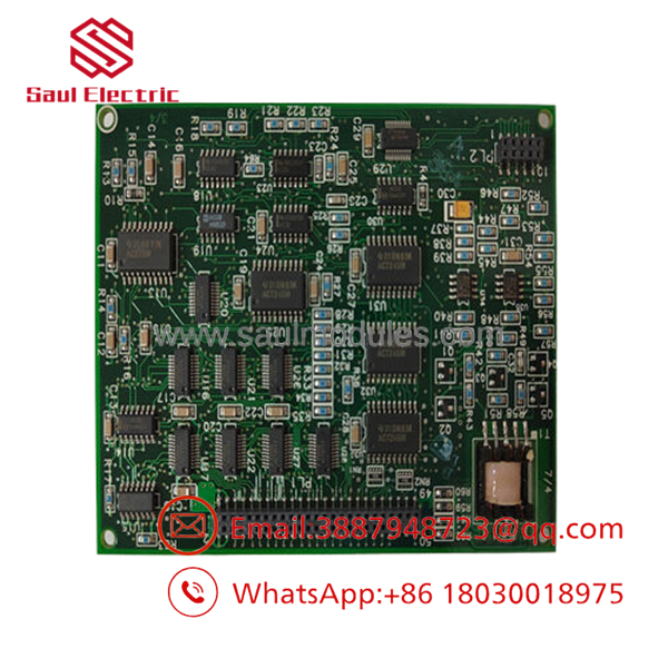
- IC660ELB912
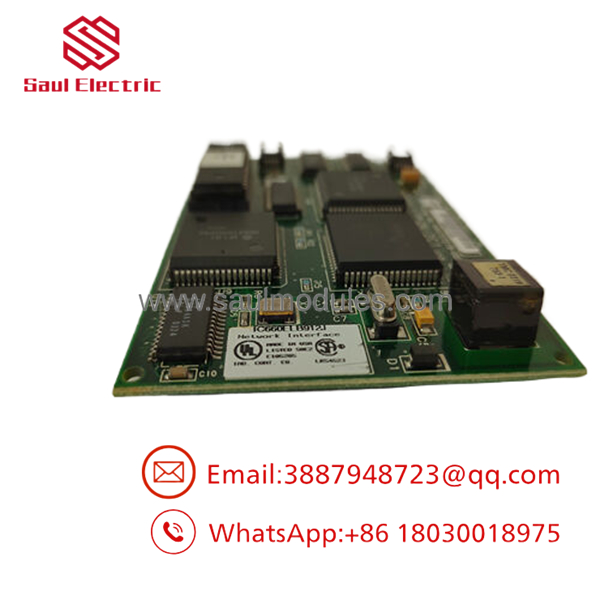
- IC660ELB912
Frequently Asked Questions (FAQ)
Can I hot-swap the electronic assembly while the block base has power?
Yes. The GE Genius I/O platform was explicitly designed to allow hot-swapping of the electronic assembly. Because all field wiring lands on the passive terminal block base rather than the electronic module itself, you can slide the card out while the base remains physically bolted to the rail. However, you must first bypass or put any critical control loops fed by these 4 channels into a manual safety hold, because removing the electronics will drop the I/O signals instantly.
Why does this module support both 115 V AC and 125 V DC operations?
The internal sensing and solid-state switching circuits inside the were engineered to handle broad electrical thresholds typical of industrial power distributions. This dual compatibility allows the exact same card model to be stocked as a universal spare across plants running standard 115 V AC utility lines, as well as heavy-duty substation layouts that rely on isolated 125 V DC battery backup banks for safety control logic.
Do I need to re-program the PLC code when swapping this card out?
No, you do not need to alter the PLC’s core application ladder code. The CPU tracks I/O points based on reference mapping addresses tied to the node’s position on the Genius bus line. As long as you configure the new surplus with the exact same Block ID and Baud Rate parameters as the failed unit, the master PLC controller will recognize the node automatically and resume standard data exchange cycles upon boot-up.
What causes a “Failed Switch” diagnostic message on this specific assembly?
A “Failed Switch” error indicates that the onboard smart diagnostic circuitry has detected a state mismatch across an output circuit’s solid-state switch. If the module sends a command to turn an isolated circuit ON, but its internal hardware check reads 0 V across the output terminal, or vice versa (such as a shorted triac feeding voltage while commanded OFF), the card triggers this alarm to notify the maintenance team of localized hardware failure.
My replacement board doesn’t communicate; how do I adjust the baud rate?
Genius blocks do not use physical hardware DIP switches or jumpers to adjust network addresses or communication speeds. You must connect a GE Genius Hand-Held Monitor (HHM) to the physical port located on the front of the block housing, or push the settings down over the network via a configuration utility inside Proficy Machine Edition. New surplus assemblies come set to factory defaults and will not communicate until you match the address to your site’s specific network requirements.



 Start Chat


