





Description
Key Technical Specifications
| Parameter | Value |
|---|---|
| Number of Channels | 8 Single-Ended Inputs |
| Input Signal Ranges | 4 to 20 mA, 0 to 20 mA, 0 to 10 V, −10 to +10 V (Configurable per channel) |
| Converter Resolution | 12-Bit Binary |
| Update Rate | 8 ms for all 8 channels (typical) |
| Input Impedance | 250 Ω for current mode, >1 MΩ for voltage mode |
| Isolation | 1,500 V AC continuous between field wiring and internal bus logic |
| External Power Requirement | 24 V DC ±10% nominal field power |
| Operating Temperature | 0 to +60 °C (32 to 140 °F) |
Product Introduction
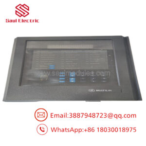
The GE Fanuc IC670ALG310-JA is an 8-channel, 12-bit analog input module belonging to the legacy Field Control distributed I/O family. Designed to sit closer to instrumentation skids, this module accurately captures variable process loops—such as pressure transmitters, temperature transmitters, and flow sensors—and encodes them into binary data for communication back to a master controller via a Field Control Bus Interface Unit (BIU).
The “-JA” suffix denotes a production revision block that upgrades internal analog-to-digital converter components to reduce thermal drift and enhance rejection of low-frequency electrical noise. Plant maintenance teams value the IC670ALG310-JA for its rugged mechanical footprint, which features a split design that allows the active electronic module to be extracted from its passive terminal block base without disrupting operational field wiring loops.
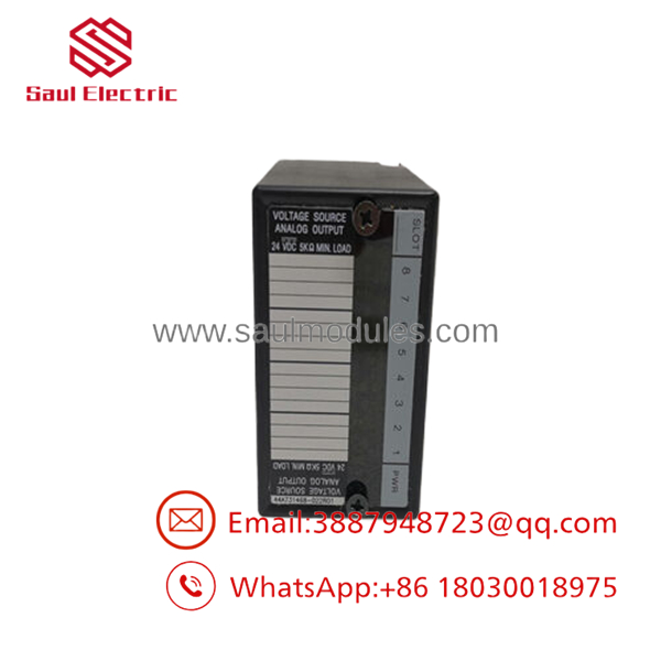
- IC670ALG310-JA
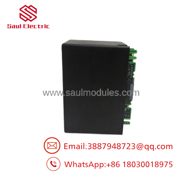
- IC670ALG310-JA
Installation & Configuration Guide
Stage 1: Pre-Installation Preparation (Estimated Time: 15 minutes)
- ⚠️ Safety First: The IC670ALG310-JA monitors instrumentation points that control live process loops. Swapping this card under active plant conditions will freeze process variables and can cause control valves or pumps to react unexpectedly. Put all associated loops into manual safety bypass. Isolate the 24 V DC field power supply and the backplane logic bus power feeding the Field Control rack. Lock out and tag out the enclosure breaker.
- Tools Required: Grounded static-dissipative ESD wrist strap, small flathead screwdriver, and Proficy Machine Edition (PME) or a Hand-Held Programmer (HHP).
- Data Backup: Open your PME configuration utility. Upload and save the master I/O hardware configuration profile. Note down the configured range parameters (e.g., 4–20 mA vs 0–10 V) and raw scaling values mapped to each of the 8 channels.
Stage 2: Removing the Old Module (Estimated Time: 5 minutes)
- Attach your ESD wrist strap to a verified chassis ground on the cabinet frame.
- Release the mechanical locking tabs located at the top and bottom of the module housing face.
- Pull the module straight out from the terminal block base using a steady, even motion to prevent bending the high-density backplane connector pins.
- Inspect the gold-plated male terminal connectors remaining on the passive base for any signs of dust, corrosion, or pin misalignment.
- ⚠️ Note: Leave the existing field wires landed on the terminal strip undisturbed; the base plate remains permanently mounted to the DIN rail.
Stage 3: Installing the New Module (Estimated Time: 10 minutes)
- Maintain your ESD grounding connection. Remove the new surplus IC670ALG310-JA module from its anti-static shielding wrap.
- Verify that any physical configuration jumpers or DIP switches on the back of the card match the old unit’s hardware profile exactly.
- Align the module housing guide rails with the channels on the terminal block base.
- Press the module firmly into the base until the internal terminal blocks lock together completely and the top/bottom mechanical tabs click shut into place.
- Self-Checklist:
- [ ] Module clicked home tightly, seating flush into the base plate.
- [ ] Rear configuration settings verified against the original board layout.
- [ ] Adjacent Bus Interface Unit connections confirmed secure.
Stage 4: Power-On & Testing (Estimated Time: 20 minutes)
- Reapply the backplane logic bus power, followed by the 24 V DC external field power loop.
- Observe the front panel diagnostic LEDs. The MODULE OK light must transition to a solid green state, indicating that internal self-tests passed.
- Establish a live software connection to the rack via PME. Download the original hardware configuration parameters to the node.
- Use a signal generator to inject a fixed 4.0 mA or 1.0 V reference signal into Channel 1. Verify that the matching register in the PLC register map reads the precise digital representation (e.g., 0 counts for a 4–20 mA scaled range). Repeat for all active channels.
- ⚠️ Troubleshooting Note: If the FIELD STATUS or MODULE OK LED illuminates red or flashes, a 24 V DC loop power outage or an out-of-bounds configuration error is present. Check for reversed signal wiring polarities at the terminal base.
Frequently Asked Questions (FAQ)
Can I hot-swap the module while the rack is powered up?
Yes, the Field Control architecture technically supports removing the electronic module from its terminal base under power. However, doing so is highly discouraged unless the process line is completely stopped or manually bypassed. The moment the electronic card is uncoupled from the base, all 8 analog telemetry signals drop to zero counts. The host controller will immediately register a loss of signal fault, which can trigger downstream emergency interlocks or trip the process.
What is the mechanical difference between the electronic module and the terminal base?
The Field Control series utilizes a two-piece design to minimize maintenance downtime. The terminal base mounts permanently onto the cabinet DIN rail and hosts all physical field wiring connections. The electronic module (the ) contains the processor, conversion circuitry, and software configurations. It slides into the terminal base, meaning you can swap failed electronics in minutes without picking up a wiring screwdriver or risking terminal assignment errors.
Why is my 4-20 mA loop reading a configuration fault after installation?
The uses software-configurable channels. If a new surplus card is inserted, it defaults to standard factory parameters (frequently 0 to 10 V mode). If you connect a 4 to 20 mA loop to a channel expected to read voltage, the card will read an unexpected current burden across its internal 250 Ω resistor and flag an input error. You must push your specific site hardware configuration from your PLC software to initialize the correct sensing modes.
Does the “-JA” revision require a different GSD file or firmware version than a baseline model?
No, the “-JA” revision is a direct form, fit, and function substitute for the base IC670ALG310 card. The suffix modification indicates internal electronic component modernizations designed to improve signal processing precision and enhance board longevity. Your existing master configuration profile, system GSD files, and PLC application program will treat the card identically without needing modifications.
What should I check if a single analog channel reads a constant maximum value (floating high)?
If a single channel locks at its maximum limit, it typically points to a broken field wire or an open signal circuit loop. Because these inputs are single-ended, an open circuit loses its ground reference and floats to its maximum voltage state due to internal pull-up bias currents. Disconnect the field line at the base plate and check the loop using a mA meter to verify that the field transmitter is actually generating a valid current loop.


 Start Chat


