





Description
Key Technical Specifications
| Parameter | Value |
| Processor Type | Intel 80386EX |
| Processor Speed | 25 MHz |
| User Execution Memory | 240 KB (bytes) available for logic program and configuration |
| Boolean Execution Speed | 0.22 \mus per typical function block / contact instruction |
| Total Register Memory (%R) | 9,999 words |
| Discrete Input/Output Capacity | 2,048 Inputs (%I) and 2,048 Outputs (%Q) max capacity |
| Analog I/O Channels | Up to 1,024 Analog Inputs (%AI) and 512 Analog Outputs (%AQ) |
| Integrated Communication Ports | 3 Ports: Port 1 (RS-232, RJ-11), Port 2 & 3 (RS-485 via 15-pin D-sub) |
| Supported Protocols | SNP, SNP-X, Serial I/O, Modbus RTU Slave (with expansion) |
| Maximum Local Base Racks | Supports 1 CPU baseplate plus up to 7 local expansion baseplates |
| Current Draw from Backplane | 890 mA from the 5 V DC backplane power rail |
Product Introduction
The GE IC693CPU363 is a high-performance, single-slot Central Processing Unit (CPU) module developed for the legacy GE Fanuc Series 90-30 programmable logic controller family. Driven by a 25 MHz Intel 80386EX microprocessor, this processing unit features an expanded 240 KB user memory structure, making it one of the most capable controller choices available for complex logic applications within the Series 90-30 matrix.
This CPU is chosen over entry-level units because of its three integrated serial communication ports, which simplify connections to local human-machine interfaces (HMIs), diagnostic computers, and variable frequency drives without requiring additional serial communication modules. Designed to seat in the dedicated CPU slot of any standard 3-slot, 5-slot, or 10-slot Series 90-30 baseplate, it supports deterministic sub-millisecond execution times for up to 2,048 discrete I/O points in high-speed manufacturing and packaging lines.
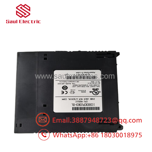
- IC693CPU363
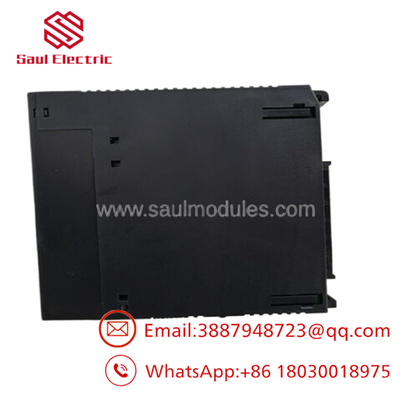
- IC693CPU363
Installation & Configuration Guide
Stage 1: Pre-Installation Preparation (Estimated Time: 15 minutes)
- ⚠️ Safety First: Disconnect and lock out the main AC or DC power feed driving the Series 90-30 power supply module on the left side of the baseplate. Working on the rack while the backplane is live can cause electronic component destruction or data corruption.
- Tools Required: Anti-static ESD grounding wrist strap, small flat-head terminal driver, and a PC running Proficy Machine Edition or Logicmaster 90 software.
- Data Backup: Connect your programming cable to the operational CPU. Run an “Upload from PLC” routine to back up the current ladder logic registers (%R), discrete statuses (%I/%Q), and hardware configuration data before physical removal.
Stage 2: Removing the Old CPU (Estimated Time: 5 minutes)
- Affix your ESD wrist strap to a verified bare-metal ground point on the control enclosure panel.
- Unplug any communication cables connected to the front 15-pin D-sub ports or the lower RJ-11 diagnostic port.
- Locate the retaining plastic clips at the very top and bottom of the module housing.
- Firmly squeeze the top and bottom clips inward to unlock the module tabs from the chassis frame.
- ⚠️ Note: Pivot the module outward away from the rack and pull it straight toward you to disengage the multi-pin connector from the backplane slot receptacle. Place the card inside an anti-static bag.
Stage 3: Installing the New CPU (Estimated Time: 10 minutes)
- Remove the new IC693CPU363 module from its protective ESD packaging sheet.
- Ensure the top and bottom extraction tabs are in their natural open position.
- Align the rear circuit board edge with the top and bottom guide tracks of Slot 1 (directly adjacent to the power supply module).
- Slide the module rearward until it meets the backplane receptacle. Apply firm, even pressure on the top and bottom face corners until you hear a distinct click, confirming the locking tabs have latched securely onto the rack frame.
- Reconnect your serial communication cables to the designated port interfaces.
Stage 4: Power-On & Configuration (Estimated Time: 15 minutes)
- Turn on the main power supply feeding the Series 90-30 baseplate.
- Observe the front-panel indicator array. The PWR and OK green LEDs must light up solid. If the OK LED remains dark or flashes, the CPU has failed its power-on self-test (POST).
- Connect your programming PC using an RS-232 to RS-485 converter utility to the 15-pin SNP port or via an RJ-11 cable to Port 1.
- Establish an online session, navigate to the target clear memory routine, and clear any existing residual configurations on the new hardware.
- Download your archived ladder program and hardware configuration file. Transition the keyswitch or software status toggle into RUN mode; the green RUN LED on the faceplate should illuminate.
- ⚠️ Troubleshooting Note: If the RUN LED flashes intermittently or fails to turn on, view the fault tables within Proficy Machine Edition. This typically indicates an I/O module configuration mismatch between your software layout and the physical cards seated in the rack slots.
Frequently Asked Questions (FAQ)
What programming software is used to configure the IC693CPU363?
This module is natively compatible with modern Emerson/GE Proficy Machine Edition (PME) software, as well as legacy DOS-based Logicmaster 90-30 and Windows-based VersaPro applications. When using Proficy, make sure to configure your target project settings to match the exact hardware catalog number IC693CPU363 to ensure compilation and variable mapping correspond to the processor’s memory limits.
Does this CPU maintain its program logic if the main rack power is shut off?
The memory map on the utilizes volatile CMOS RAM to maintain rapid execution loops. The configuration data and running code are retained during a power shutdown by a lithium battery backup link located behind the door of the adjacent power supply module. If that battery dies while power is down, your logic program will clear out. To avoid this, you can write your final program into the non-volatile EEPROM memory layer using the software’s flash-burning utility.
Can I plug this module into any slot on a Series 90-30 baseplate?
No. The central processing unit must be inserted into Slot 1 of a CPU-style baseplate (such as the IC693CHS391 10-slot baseplate), which sits directly to the right of the power supply module. It cannot be inserted into expansion baseplates or standard I/O slots, as those positions lack the necessary backplane bus line architecture required to communicate with master processor components.
What is the exact purpose of the three onboard serial communication ports?
- Port 1 (RJ-11): Located at the bottom corner, this is a dedicated, short-distance RS-232 port primarily configured for local engineering terminal hookups and laptop diagnostic diagnostics.
- Port 2 & Port 3 (15-pin D-sub): These use RS-485 differential signaling, allowing them to communicate over longer distances (up to 4,000 feet) with plant network devices using GE’s proprietary SNP (Series Ninety Protocol) or SNP-X multidrop communication architecture.
Since the Series 90-30 product line is discontinued by GE/Emerson, what is the status of this unit?
This module is available as New Original / New Surplus inventory sourced from climate-controlled warehouse reserves, surplus system assemblies, and canceled plant retrofits. While Emerson (who acquired GE Intelligent Platforms) has transitioned active production to newer controller generations like the PACSystems RX3i, we carry fully validated, tested legacy components backed by our independent 1-year operational warranty to support operational facilities running legacy architectures.

 Start Chat


