





Description
Key Technical Specifications
| Parameter | Value |
|---|---|
| Manufacturer | GE Fanuc |
| Model Number | IC697ALG320 |
| Product Type | High-Level Analog Output Module |
| PLC Platform | Series 90-70 PLC |
| Number of Output Channels | 4 independently configurable channels |
| Output Types | Voltage or Current |
| Voltage Output Range | -10 V to +10 V |
| Current Output Range | 0–20 mA, 4–20 mA (default), up to 22.5 mA |
| D/A Resolution | 16-bit with 14-bit monotonicity |
| Conversion Time | Approximately 2 ms |
| Isolation | Outputs isolated from the VME backplane |
| Backplane Power | +5 V DC, 1.66 A (8.3 W maximum) |
| Field Power | 24 V DC recommended for current outputs |
| Installation | Single slot in Series 90-70 rack |
Product Introduction
The GE IC697ALG320 is a 4-channel high-level analog output module for the GE Fanuc Series 90-70 PLC platform. It converts PLC output data into precise voltage or current signals for process control applications including variable frequency drives, valve positioners, actuators, and instrumentation.
Each output channel can be configured independently for voltage or current operation, making the module suitable for mixed analog control systems. Factory calibration data is stored in onboard EEPROM, eliminating routine field calibration after installation. Before replacement, verify the configured output ranges and field power supply to maintain system compatibility.
Troubleshooting Quick Reference
| Symptom | Possible Cause | Relevance to this Part | Quick Check Method | Recommendation |
|---|---|---|---|---|
| All analog outputs read zero | Missing backplane or field power | ❌ Low | Measure +5 V DC backplane and 24 V DC field supply | Restore power before replacing the module |
| One output channel remains at 0 V | Incorrect PLC configuration | ✅ Medium | Verify the assigned %AQ register and output configuration | Correct PLC programming and retest |
| 4–20 mA output reads incorrectly | Missing field power | ✅ High | Measure the external 24 V DC supply at the output terminals | Restore field power and verify wiring |
| Output signal unstable | Electrical noise or poor grounding | ❌ Low | Inspect shield grounding and cable routing | Use shielded cable with single-point grounding |
| Module fault LED illuminated | Internal analog circuitry failure | ✅ High | Review PLC diagnostics and module status | Replace the module after confirming external circuits |
| Output saturated at maximum | Incorrect engineering scaling | ✅ Medium | Compare PLC scaling with field instrument requirements | Correct scaling parameters |
| No response from field device | Open output wiring | ❌ Low | Measure output voltage/current directly at the module terminals | Repair field wiring before replacing hardware |
Technical Note: In most installations, analog output problems are caused by configuration errors, missing 24 V DC field power, damaged wiring, or incorrect scaling—not by failure of the IC697ALG320 itself. Confirm these items before replacing the module.
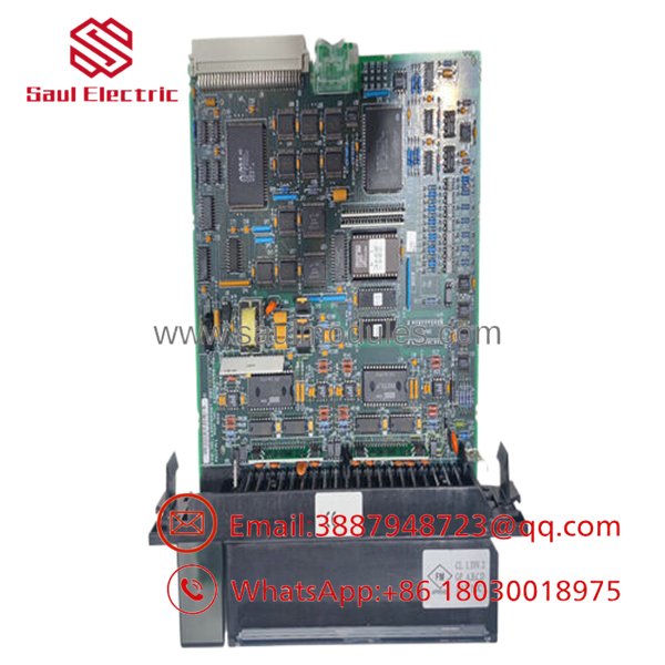
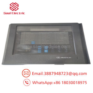
- IC697ALG320
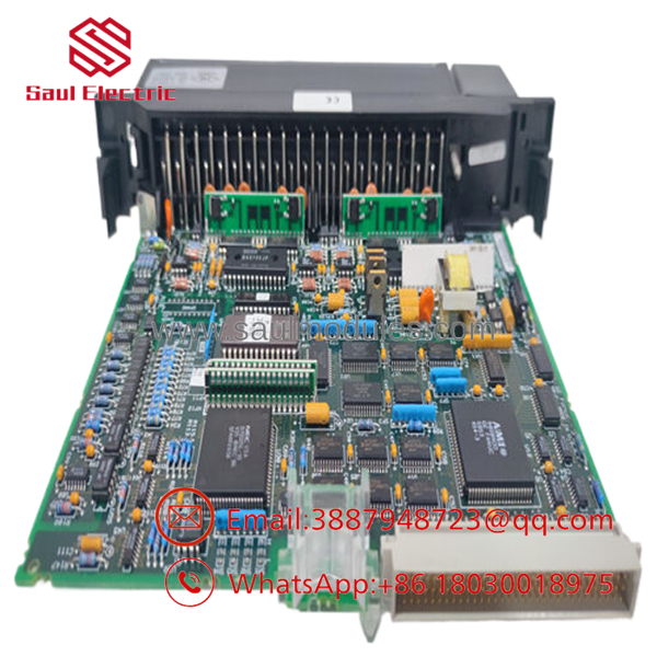
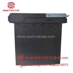
- IC697ALG320
Frequently Asked Questions (FAQ)
Q1. What is the IC697ALG320 used for?
The converts PLC data into analog voltage or current signals for controlling field devices such as variable frequency drives, control valves, actuators, and process instrumentation.
Q2. How many analog outputs does this module provide?
The module provides four independently configurable analog output channels. Each channel can be configured individually for voltage or current output.
Q3. Can each channel use a different output type?
Yes.
One channel can operate at ±10 V, while another simultaneously provides 4–20 mA or 0–20 mA output, depending on the application configuration.
Q4. Is field power required?
Yes.
Current output operation requires an external 24 V DC field supply. If this supply is missing, current outputs may not operate correctly even though the PLC detects the module normally.
Q5. Why is New Surplus inventory less expensive than factory inventory?
Most New Surplus modules originate from canceled projects, OEM spare inventories, or unused maintenance stock. They have not been installed in production service but are no longer in active factory production.
Q6. What should I verify before ordering?
Verify:
- Exact model number ()
- Series 90-70 rack compatibility
- Output type requirements (Voltage or Current)
- External 24 V DC field power
- PLC program and %AQ addressing
- Terminal wiring
These checks prevent unnecessary commissioning delays.
Q7. What warranty is typically available?
Most industrial automation suppliers provide a 12-month warranty for verified New Surplus or professionally tested modules. Request a functional test report, calibration verification, and photographs before shipment.
Quality Inspection & Testing SOP
1. Inbound Inspection & Traceability
- Verify GE Fanuc labels, serial numbers, and hardware revision.
- Inspect PCB assemblies, connectors, and housing for corrosion, bent pins, scratches, or repair evidence.
- Confirm traceability documentation and anti-counterfeit markings.
- Record serial numbers before testing.
2. Live Functional Testing
- Install the module in an in-house GE Series 90-70 PLC test rack.
- Verify successful module recognition during startup.
- Test all four output channels in both voltage and current modes.
- Verify ±10 V, 0–20 mA, and 4–20 mA outputs using calibrated measurement equipment.
- Perform continuous operation for more than 24 hours while monitoring output stability.
- Generate a documented functional test report.
- Test photos and videos are available upon request.
3. Electrical Parameter Testing
- Perform insulation resistance testing using a 500 V Megger where applicable.
- Verify chassis ground continuity.
- Measure voltage and current outputs using a calibrated Fluke 115 digital multimeter.
- Confirm output accuracy across the full operating range.
4. Firmware & Configuration Verification
- Verify hardware revision.
- Confirm EEPROM calibration data is retained.
- Document the module identification before shipment.
5. Final QC & Packaging
- Final inspection and QC approval.
- Seal the module inside an ESD-safe bag.
- Protect with anti-static foam, bubble wrap, and a heavy-duty corrugated shipping carton.
- Apply a dated QC Passed label.
Technical Pitfalls & Survival Guide
❗ Don’t Forget the External 24 V DC Supply
I’ve seen technicians replace a perfectly good analog output module because every 4–20 mA channel measured zero.
The problem wasn’t the module—it was a blown fuse feeding the external 24 V DC field supply.
❗ Verify the Output Range
Before removing the original module, document whether each channel is configured for ±10 V, 0–20 mA, or 4–20 mA.
Installing the replacement with the wrong configuration can cause valves to move unexpectedly or drives to receive incorrect speed references.
❗ Check PLC Scaling First
A control valve opening only halfway doesn’t always indicate a hardware problem.
Verify the %AQ scaling in the PLC program before replacing the analog output module. Incorrect engineering units are a common source of commissioning problems.
❗ Inspect Shielding and Grounding
Don’t route analog output cables alongside high-current motor cables.
Electrical noise can introduce unstable control signals that resemble module faults. Use shielded cable and terminate the shield at one end unless your site standard specifies otherwise.
❗ Electrostatic Discharge (ESD)
Always wear a grounded wrist strap.
I once watched a technician install a replacement analog output card directly from its shipping box during a dry winter shutdown. The module powered up normally but developed intermittent output drift a few days later. Static damage isn’t always immediate, but it can permanently weaken analog circuitry.
Keep these checks in mind and you’ll avoid most analog commissioning problems, reduce unnecessary module replacements, and shorten plant startup time.

 Start Chat


