





Description
Key Technical Specifications
| Parameter | Value |
| Total Card Capacity | 17 physical module slots + 1 dedicated Power Supply slot |
| Mounting Orientation | Rear wall / panel screw plate mount |
| Backplane Bus Type | VME64 standard format supporting multi-byte throughput bursts |
| Compatible Modules | RX7i CPUs (e.g., CRE040), Series 90-70 I/O cards, VMIC modules, VME devices |
| Module Width Support | Accommodates single-width and double-width hardware variants |
| Power Distribution Paths | Dual bus distribution layout for 3.3 V DC and 5 V DC supply tracks |
| Thermal Protection Requirement | Requires a dedicated fan cooling unit assembly under full module loads |
| Physical Weight | 14.99 lbs (6.80 kg) |
| Construction Material | Heavy-gauge industrial-grade aluminum framework chassis |
Product Introduction
The GE IC698CHS217 is a heavy-duty 17-slot rear-mount chassis baseboard designed to serve as the structural and communication backbone for the PACSystems RX7i controller platform. Equipped with a high-performance VME64 backplane, this chassis provides up to four times the bandwidth of standard, legacy VME architectures, enabling deterministic, sub-millisecond data transfer for high-throughput automated processes.
Industrial operators deploy the IC698CHS217 in large-scale applications—including water treatment facilities, metal foundries, and gas turbine control decks—because it bridges legacy and modern hardware. The backplane natively supports high-speed RX7i Pentium-M processor cards alongside legacy Series 90-70 I/O modules and standard VMIC cards, allowing facilities to execute system overhauls without discarding active, field-wired termination blocks.
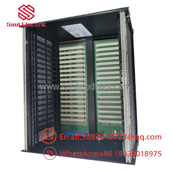
- IC698CHS217
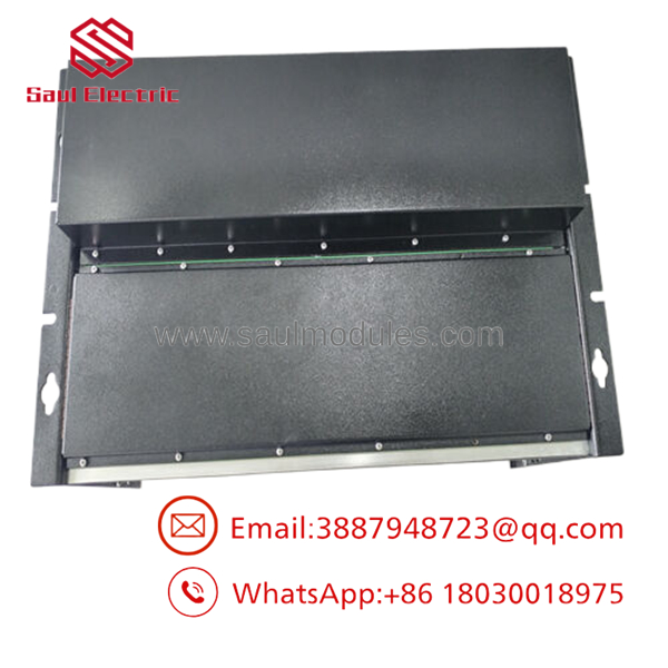
- IC698CHS217
Installation & Configuration Guide
Stage 1: Pre-Installation Preparation (Estimated Time: 30 minutes)
- ⚠️ Safety First: Shut off and isolate all incoming AC/DC power lines feeding the control cabinet area. Verify that no live potential remains on the supply wires before mounting hardware.
- Tools Required: PH2 cross-tip screwdriver, metric socket wrenches, fine-bristle anti-static brush, and a digital multimeter.
- Chassis Inspection: Inspect the rear backplane pin matrix. Ensure no pins are bent, misaligned, or contaminated with industrial grime before sliding modules into place.
Stage 2: Mounting the Chassis Frame (Estimated Time: 20 minutes)
- Mark the mounting drill configuration on the backplate of your NEMA enclosure using the chassis pre-drilled screw plates as a template.
- Secure the 14.99-pound IC698CHS217 frame using correct industrial-grade bolts and lock washers to handle ambient vibration.
- ⚠️ Grounding Requirement: Clean away any paint around the designated chassis ground lug. Connect a heavy, low-impedance ground strap from the chassis frame directly to the primary substation ground plane terminal pad to manage EMI/RFI noise.
- Mount the dedicated RX7i cooling fan assembly unit directly underneath the rack frame layout.
- ⚠️ Cooling Note: The processing density of an RX7i CPU creates significant thermal load; operating this chassis without active fan ventilation will lead to localized heat pockets and premature card failures.
Stage 3: Board Seating & Hardware Configuration (Estimated Time: 20 minutes)
- Slide the high-capacity RX7i power supply module into its dedicated slot on the far left of the backplane. Secure its top and bottom face plate screws to lock it into position.
- Insert your chosen CPU (e.g., IC698CRE040) into Slot 1.
- Populate the remaining slots with your Series 90-70 or VMIC VME network cards, tracking your original physical I/O layout mappings.
- Push each module firmly until its backplane connectors engage with the rack’s VME64 pin sockets. Flip the upper and lower injection/ejection handles inward until they click flush.
Stage 4: Power-On & Operational Validation (Estimated Time: 15 minutes)
- Connect the power mains wires to the input terminal block on the RX7i power supply card.
- Energize the circuit breaker.
- Check the power indicator LEDs on both the supply module and the active CPU board. The OK and running status lights should illuminate solid green.
- Establish a configuration link via Proficy Machine Edition. Upload the hardware status report to ensure the software successfully maps all 17 slots without communication timeouts or backplane bus errors.
- ⚠️ Troubleshooting Note: If a slot returns an unreadable module error or a VME bus fault is generated, shut off power and pull the affected card. Check for hidden debris inside the backplane connector or an incorrect slot-addressing jumper configuration on the module’s side profile.
Frequently Asked Questions (FAQ)
What is the functional upgrade advantage of the VME64 backplane in this rack?
The VME64 architecture integrated into the IC698CHS217 backplane provides significantly wider data channels and faster clock transfer capabilities than legacy VME structures. It transfers data at up to four times the bandwidth of older Series 90-70 racks. This lets the system handle complex, processing-heavy control logic, high-density analog loops, and intensive web-server data tracking simultaneously without causing communication bottlenecks.
Can I populate this chassis with older Series 90-70 I/O modules?
Yes, the backplane is explicitly designed with backward compatibility in mind. You can plug standard single-width or double-width Series 90-70 discrete and analog I/O modules directly into the slots. This allows plants running legacy 90-70 controllers to step up to high-speed PACSystems RX7i processors without needing to re-wire their field terminal assemblies.
Why does this specific 17-slot chassis require a separate fan cooling kit?
High-performance RX7i components, especially Pentium-M based processors and high-output power supplies, generate significant heat during continuous operation. In a dense 17-slot footprint, natural convection cooling is insufficient. A dedicated fan cooling kit must be installed to maintain constant air circulation across the card components and prevent thermal shutdown or components tracking failures.
Is Slot 0 or Slot 1 handled differently on this backplane layout?
Yes. The dedicated power supply module occupies its own designated slot on the far left. Slot 1 is the primary controller slot, reserved for the master PACSystems RX7i CPU card. The remaining slots handle standard I/O communication, network adapters, and auxiliary VME modules based on your hardware configuration parameters defined in Proficy Machine Edition.
What is the current availability status of this chassis since it is discontinued?
Because Emerson/GE Fanuc has transitioned its active production lines to the modular PACSystems RX3i platform, the legacy RX7i rack is officially discontinued. We carry clean, verified New Original / New Surplus units sourced from plant maintenance reserves and canceled automation projects. Every backplane undergoes extensive physical inspections and multi-module electronic bench tests to guarantee operational reliability, and each unit is backed by our full 1-year warranty.


 Start Chat


