





Description
Product Introduction & Engineering Value
The GE IS200BPIAG1AEB sits at an important boundary in a Mark VI drive system: it carries signals between the control electronics and the IGBT power bridge. The board handles gate-drive and shunt-fault signals while also receiving bridge-related feedback and control information.
This is not a generic interface PCB. The BPIA hardware has dedicated connections for the three drive phases and includes isolated power circuitry, gate-driver interfaces, and VCO feedback circuits. Exact part-number and revision matching should therefore be completed before replacement.
Technical Specifications
| Parameter | Specification |
|---|---|
| Manufacturer | General Electric |
| Part Number | IS200BPIAG1AEB |
| Product Series | Mark VI Speedtronic |
| Functional Acronym | BPIA |
| Board Type | Bridge Personality Interface Board |
| Primary Application | IGBT AC drive interface |
| Drive Configuration | Three-phase |
| Board Connectors | 7 |
| Rack Connector | P1 |
| Phase Connections | APL, BPL, CPL, AAPL, BAPL, CAPL |
| Transformers | 3 |
| Transistors | 6 |
| Memory Device | 1024-bit device for board/revision information |
| PCB Coating | Normal coating |
| Revision History | 3 revisions reported |
The P1 connector interfaces with the rack and carries signals including gate-drive, shunt-fault, bridge-control, and application data. Six additional connectors interface with the A, B, and C phase IGBT circuitry.
Technical references also identify six independent IGBT gate-driver circuits, three VCO feedback circuits, and nine isolated power supplies on the BPIA design.
Engineering note: Some reseller pages attach unrelated Ethernet, analog-output, or general-purpose digital-I/O descriptions to this part number. Those claims are inconsistent with the documented BPIA function and should not be used for engineering substitution decisions.
Field Application & the “Trench” Experience
A BPIA board can become the suspect when an IGBT drive reports bridge faults, gate-drive problems, or unexplained phase behavior. But replacing it blindly is a poor diagnostic method.
Imagine a maintenance team troubleshooting a Mark VI drive during an outage. The IS200BPIAG1AEB is showing abnormal bridge-related behavior. Before changing the board, the technician checks the phase connections, gate-drive interfaces, shunt-fault paths, and associated power electronics. The spare BPIA is then compared against the installed board and its revision before being fitted.
After replacement, the team does not stop at “board powered up.” They verify the gate-drive interface, feedback behavior, fault indications, and drive operation under controlled conditions.
Niche application scenarios
- Three-phase IGBT AC drive bridge interface: connecting Mark VI control electronics with the drive’s power electronics.
- IGBT gate-drive control: supporting six independent gate-driver circuits associated with the three-phase bridge.
- Drive bridge fault monitoring: carrying shunt-fault and related bridge feedback signals back toward the control system.
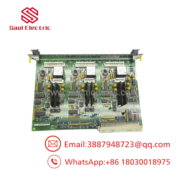
IS200BPIAG1AEB
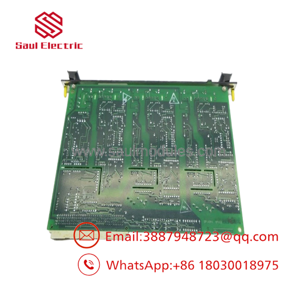
IS200BPIAG1AEB
Transparency SOP: QA & Testing
For IS200BPIAG1AEB stock, a useful QA process is:
- Part-number verification — Confirm the complete
IS200BPIAG1AEBdesignation and revision markings. - Connector inspection — Check P1 and all six phase-related connectors for bent pins, contamination, oxidation, or mechanical damage.
- PCB inspection — Examine transformers, transistors, resistor networks, memory device, solder joints, and PCB traces.
- Electrical screening — Check for shorts and abnormal resistance paths before applying operating power.
- Gate-drive verification — Where suitable test equipment is available, verify the applicable gate-drive interface circuits.
- Feedback verification — Check the applicable VCO feedback paths and bridge-fault circuits.
- System test — In a compatible Mark VI/drive test environment, confirm normal initialization and controlled drive operation.
- Traceability — Record revision, condition, test scope, and warranty information.
For New Surplus units, request photographs of the actual board rather than relying exclusively on catalog photographs.
The Veteran’s Tech Trap Guide
⚠️ Trap #1 — Don’t confuse BPIA with BPIB.
GE has multiple Bridge Personality Interface variants. A similar-looking BPI board is not automatically an electrical substitute.
⚠️ Trap #2 — The six phase connectors matter.
The APL, BPL, CPL, AAPL, BAPL, and CAPL connections are associated with the three-phase IGBT interface. Label every cable before removal.
PRO TIP: Photograph the P1 connection and all six phase connectors before disconnecting anything. A wiring mistake at the bridge interface is considerably more expensive than a labeling mistake in the maintenance log.
⚠️ Trap #3 — Treat it as ESD-sensitive power-control electronics.
Do not handle the PCB by exposed components or connectors. Use appropriate ESD controls, and inspect the board carefully before inserting it into the rack.
⚠️ Trap #4 — Check revision compatibility.
Available references report three revisions for this part number and state that the first two revisions are backward-compatible. Do not assume every revision is interchangeable.
Dynamic FAQ
What is the GE IS200BPIAG1AEB?
The is a GE Mark VI Bridge Personality Interface Board (BPIA) used to interface control electronics with the power electronics of an IGBT AC drive.
How many connectors does the board have?
The board has seven connectors: one primary P1 rack connector plus six connectors associated with the A, B, and C phase IGBT interfaces.
What does the BPIA board interface?
It interfaces the Mark VI control electronics with the power electronics of a three-phase IGBT AC drive. The interface includes gate-drive signals, shunt-fault signals, bridge-control information, and feedback.
Is the IS200BPIAG1AEB interchangeable with another BPIA board?
Not automatically. Verify the complete part number, hardware revision, drive application, connector configuration, and system documentation before substitution.
How should a New Surplus IS200BPIAG1AEB be verified?
Request photographs of the actual board, including its GE identification label, revision markings, connectors, and component side. Confirm that the unit has not previously been installed, repaired, or modified.
What warranty should I confirm?
Confirm the warranty period, DOA policy, return conditions, and the actual testing performed. The supplier should explicitly identify the condition as New Surplus, Refurbished, or Used and provide test documentation when available.



 Start Chat


