





Description
Product Introduction & Engineering Value
The IS200BPIBG1A sits at a critical interface point in GE Mark VI IGBT drive architecture. It conditions control signals and handles fault-related information between the turbine-control electronics and the IGBT drive bridge. The board also processes phase and DC-link sensing signals.
This is not a generic I/O card. Its replacement must match the installed Mark VI configuration. GE documentation identifies the BPIB board as a VME-mounted assembly with dedicated connections to Gate Driver and Shunt Feedback boards.
Technical Specifications
- Manufacturer: General Electric
- Part Number: IS200BPIBG1A
- Series: Mark VI Speedtronic
- Assembly Level: IS200
- Functional Acronym: BPIB
- Board Type: IGBT Drive Bridge Personality Interface / Phase Logic Module
- Mounting: VME-type rack
- Gate Driver Interface: Six plug connectors
- Phase/DC-Link Sensing: Five stab-on connections
- Logic Processing: EPLD-based phase logic
- Memory: Serial 1024-bit memory device for board identification/revision information
- Manual Reference: GEI-100266
The board has no LEDs, fuses, or TP test points according to the available technical documentation. Its component population includes more than 30 integrated circuits, three transformers, four transistors, and 16 resistor-network arrays.
Drive Configuration
| Configuration | Driver Boards Supported |
|---|---|
| Single bridge | Up to 3 |
| Parallel bridge | Up to 6 |
The BPIB architecture supports both single-bridge and parallel-bridge arrangements.
Important: Some secondary-market listings publish electrical specifications that conflict with the Mark VI BPIB documentation. Do not use generic listings to establish input voltage, output-current, isolation-voltage, or response-time specifications for this exact board. Use GEI-100266 and the applicable drive documentation for commissioning values.
Field Application & the “Trench” Experience
A turbine drive begins reporting intermittent bridge faults during startup. The Gate Driver boards appear healthy, but the controller continues receiving fault indications.
The maintenance team does not immediately replace the BPIB. They first inspect the Gate Driver connections, phase-sensing wiring, DC-link sensing, and the board’s P1 interface. The IS200BPIBG1A is then compared with the site’s spare by checking the complete board identification and connector arrangement.
That approach is important because the BPIB is specifically involved in fault capture, signal conditioning, and bridge feedback paths. A fault reported through the BPIB does not necessarily mean the BPIB itself is defective.
Specific application scenarios:
- GE Mark VI IGBT drive bridge fault handling
- Gas-turbine variable-speed drive maintenance
- Parallel IGBT bridge control and feedback
- Gate Driver/Shunt Feedback interface troubleshooting
- DC-link and three-phase bridge sensing
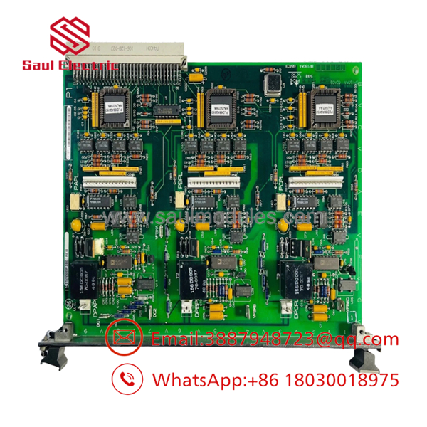
IS200BPIBG1A
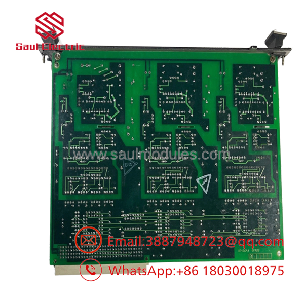
IS200BPIBG1A
Transparency SOP: QA & Testing
For IS200BPIBG1A, the QA process should focus on interface integrity and logic functionality.
- Part-number verification — Confirm IS200BPIBG1A and functional revision A.
- Physical inspection — Examine the VME edge connector, six plug connectors, five stab-on sensing connections, PCB traces, transformers, ICs, and solder joints.
- Memory identification — Verify the presence and condition of the serial identification/revision memory device.
- Connector inspection — Check for bent pins, oxidation, cracked housings, contamination, and mechanical damage.
- Functional testing — Where appropriate Mark VI test equipment is available, verify signal-conditioning and fault-interface functions against GE documentation.
- Final traceability — Record actual-unit photographs, revision information, test results, and stock condition.
New Surplus: confirm that the actual PCB is unused and determine whether it has ever been installed or energized.
Refurbished: request the repair history, replaced components if applicable, functional-test procedure, and measured results.
The Veteran’s Tech Trap Guide
⚠️ Trap #1 — Don’t confuse BPIB with BPIA.
Both are Mark VI IGBT drive bridge personality interface boards, but they are different GE part numbers. The installed configuration must determine the replacement. GE’s Mark VI catalog lists them separately.
⚠️ Trap #2 — Don’t ignore the five sensing connections.
The BPIB uses stab-on connections for Phase A, B, C and DC-link positive/negative sensing. Poor contact or incorrect reconnection can create misleading bridge faults.
⚠️ Trap #3 — No LEDs does not mean no diagnostic capability.
The board has no onboard LEDs, fuses, or TP test points. Troubleshooting therefore depends heavily on system diagnostics, external measurements, and the connected Gate Driver/Shunt Feedback circuitry.
PRO TIP: Photograph the P1 connector area and all six plug connections before removal. On a Mark VI drive, connector identification is more useful than relying on memory during a short outage window.
Dynamic FAQ
Q: What is the GE IS200BPIBG1A?
A: It is a GE Mark VI IGBT Drive Bridge Personality Interface Board, also described as a Phase Logic Module.
Q: What does the BPIB board actually do?
A: It conditions P1 logic signals for Gate Driver and Shunt Feedback interfaces, captures certain bridge faults, and processes phase/DC-link feedback signals.
Q: How many Gate Driver boards can it support?
A: The documented architecture supports up to three boards in a single-bridge configuration and up to six in a parallel-bridge configuration.
Q: Does IS200BPIBG1A have LEDs or fuses?
A: No. Available technical documentation specifically states that the board has no LED indicators, fuses, or TP test points.
Q: What should I verify before ordering a replacement?
A: Confirm the complete part number, functional revision, VME interface, connector arrangement, and the single- or parallel-bridge configuration.
Q: How should New Surplus authenticity and Refurbished quality be verified?
A: Request actual-unit photographs, confirmation of unused status for New Surplus, or a documented repair/test report for Refurbished units. Also confirm the warranty period and DOA/return terms in writing.




 Start Chat


