





Description
Product Introduction
The GE IS200PSCDG1ADB (functionally designated as the PSCD board) is a power supply and contactor driver board used in GE Speedtronic Mark VI turbine control cabinets and EX2000 excitation drive systems. It converts DC link power into stable, regulated control voltages required by adjacent processing, gate driver, and logic cards.
Unlike generic DC-DC converters, the PSCD board features an onboard buck converter delivering 105V DC specifically for driving main line contactors (like the MDA contactor), alongside an isolated 70V DC rail for trip permissive circuits. Utilizing Pulse Width Modulation (PWM), the board limits thermal dissipation and electrical stress during contactor pickup and hold cycles, maintaining operational reliability inside crowded drive enclosures.
Key Technical Specifications
| Parameter | Specification / Value |
| Manufacturer | General Electric (GE) |
| Part Number | IS200PSCDG1ADB (PSCD Group 1) |
| System Compatibility | Mark VI Speedtronic / EX2000 Excitation Systems |
| Nominal Input Voltage | 80 to 400 VDC (Transient tolerance up to 600 VDC) |
| Main Output Voltage Rails | +5 VDC, ±15 VDC, ±24 VDC for control logic boards |
| Auxiliary Output Voltage | 105 VDC (Contactor supply via buck converter, 0.75A DC max) |
| Isolated Output Voltage | 70 VDC (Powers trip permissive / 86 device relay loops) |
| Gate Driver Power Output | 17.7 VAC Square Wave via high-frequency transformers |
| Protection Features | Onboard MOVs, high-voltage electrolytic capacitors, 5A line fuses |
| Operating Temperature | 0°C to +70°C (32°F to 158°F) |
Application Scenarios & The “Trench” Experience
Picture this: It’s 2:00 AM on a blistering summer night during peak air conditioning load. A 250MW gas turbine trips unexpectedly during a run-up command because the main field contactor fails to seat properly. Diagnostics point to a collapsed 105V DC driver rail on the excitation cabinet. The original PSCD card blew its internal buck converter switching transistor, taking out the K86 emergency stop permissive loop along with it. The plant faces thousands of dollars per minute in unsupplied power fines. Having a drop-in IS200PSCDG1ADB card on site lets the instrument technician isolate DC link power, pull the faulty board, verify pin jumpers, and restore field contactor control in under 30 minutes.
- Gas Turbine Speedtronic Mark VI Racks – Provides steady DC power rails (+5V, ±15V, ±24V) to core processing cards (LDCC, TCCB) and controls run-permissive safety relays.
- EX2000 Excitation Systems – Drives pulse-width modulated current to main line contactors and gate drive boards (GDDD) for power bridge synchronization.
- Large Industrial Synchronous Motor Drives – Supplies isolated 70V DC power to field-discharge permissive loops and safety interlocks.
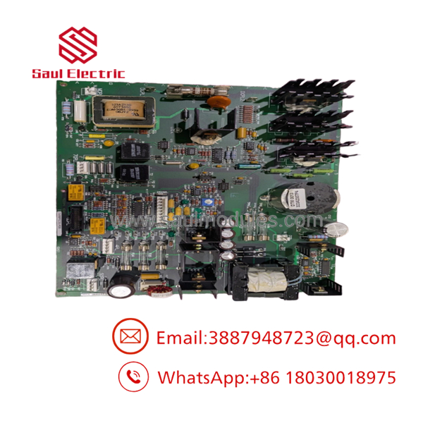
IS200PSCDG1ADB
Transparency SOP: Quality Assurance & Testing
We don’t just ship boxes; we test them on actual GE Mark VI and EX2000 test benches before they leave our facility.
- Inbound Visual & Mechanical Inspection: Physical check under magnification for leaking electrolytic capacitors, burned trace pads, damage to heat sink mounts, and fuse integrity (5A fuses).
- DC Link High-Voltage Insulation Test: Megger check across input stab-on terminals (DCPL1/DCPL2) to verify dielectric isolation between high-voltage DC paths and frame ground.
- Power-On Voltage Rail Audit: Board energized with a variable DC link input (swept from 80V to 400V DC). We measure output stability across the +5V, ±15V, ±24V, 70V, and 105V DC channels under full load resistor banks.
- Contactor Relay Switching Test: Signals injected via terminal connectors (2PL, 70PL) to verify proper actuation of onboard relays (K1, K86) and optical coupling paths.
- Anti-Static Sealing & Safe Packaging: Cleared of static charges, vacuum-sealed in an ESD shielding bag with desiccant, and packed inside custom foam boxes.
The Veteran’s Tech Trap Guide (Crucial Value-Add)
- ⚠️ Watch Out for High DC Link Voltages!
The PSCD board receives power directly from the main DC link (up to 400V DC nominal, with 600V transients). Bleed down the main capacitor bank and verify zero voltage across terminals
DCPL1 (+)andDCPL2 (-)using a safety meter before touching the board. Trust me, those big electrolytic capacitors store enough energy to arc right through a standard screwdriver. - ❗ Never Override Onboard 5A Fuses with Wire Wraps
The board contains three prominent 5A line fuses near the bottom corner. If one of these fuses blows, it indicates a dead short in the downstream 105V contactor coil or gate driver supply. Installing a higher-amp fuse or bridging the holder will vaporize the PCB copper traces instantly when 400V DC link power hits.
- ⚠️ Verify Wire Harness Placement Across Connectors
This board relies on multiple pin headers (
PPL,SQPL,2PL,4PL,70PL) to distribute power across the system. Reversing or offsetting a ribbon cable by one pin column on the2PLconnector will dump high-voltage rails directly into 5V digital logic on the LDCC processor card. Double-check keying slots! - ❗ Inspect Heat Sink Isolation
The board uses ten aluminum heatsinks to dissipate heat from power switching devices. In dirty plant environments, conductive dust (like carbon or metallic flakes) can bridge the gap between heat sink fins and surrounding surface-mount resistors. Blow out the cabinet with dry nitrogen prior to seating the board.
Frequently Asked Questions (FAQ for Conversion)
Q: What is the exact purpose of the 105V DC output on the IS200PSCDG1ADB board?
A: The 105V DC supply is generated by an onboard buck converter fed directly from the main DC link. It is sized to deliver up to 0.75A DC specifically to power the main contactor coils (such as the MDA contactor) during system run sequences.
Q: Can I use an IS200PSCDG1ADB in place of an older PSCDG1A board?
A: Yes. “IS200PSCDG1ADB” represents the full functional part number, where D indicates the functional revision level and B indicates the PCB artwork revision. GE designed these revisions to remain backward-compatible with earlier Group 1 (G1A) installations.
Q: What do the onboard relays K1 and K86 do?
A: Relay K1 is driven by the main processor board (LDCC) to command system run state and enable the contactor driver. Relay K86 functions as the master emergency stop permissive; dropping out K86 cuts power to the regulator circuits immediately.
Q: Does this board require software flashing or IP configuration?
A: No. The is a hardware-level power supply and driver card. It does not run a standalone operating system or store IP addresses; it begins regulating power automatically as soon as DC link voltage is applied.
Q: Why buy New Surplus or Tested Refurbished stock over ordering direct from OEM?
A: Legacy Speedtronic Mark VI and EX2000 hardware face long factory production cycles and inflated emergency order lead times. Sourcing pre-tested surplus stock allows you to keep critical power generation equipment online without waiting months for a replacement power board.



 Start Chat


