





Description
Product Introduction & Engineering Value
The GE IS200SCNVG1ADC is a specialized Mark VI interface board, not a general-purpose I/O module. Its job is to connect the control electronics with the SCR-Diode bridge circuitry used in Innovation Series converters. The board includes SCR gate-drive, current-sensing, voltage-feedback, DC-link feedback, and dynamic-braking interface circuitry.
That makes exact identification particularly important. The board is documented for Slot 6 of the Innovation Series rack and connects through J15 on the IS200CABP control assembly backplane. A replacement should therefore be checked against the actual rack position, board revision, connectors, and converter configuration before installation.
Technical Specifications
| Parameter | Specification |
|---|---|
| Manufacturer | General Electric |
| Part Number | IS200SCNVG1ADC |
| Series | Mark VI / IS200 |
| Functional Acronym | SCNV |
| Board Type | SCR-Diode Converter Interface Board |
| Application | Innovation Series converters |
| Converter Rating | 1000–1800 A stand-alone SCR-Diode converters |
| Rack Position | Slot 6 |
| Backplane Connector | 128-pin P1 |
| Board Connection | J15 on IS200CABP |
| SCR Gate Drives | 3 |
| Input Current Sensing Circuits | 3 |
| Line-to-Line Voltage Feedback | 2 |
| DC-Link Voltage Feedback | 1 |
| Dynamic Braking IGBT Interface | 1 gate-driver circuit |
The board is also reported to include six plug connectors associated with current shunts, gate drivers, and the DC link. Its identification and revision information are stored in an add-only memory device accessed through the P1/BRDID interface.
Field Application & the “Trench” Experience
Here is where this board gets interesting.
Suppose an Innovation Series converter begins reporting inconsistent bridge behavior during a maintenance run. The first instinct may be to blame an SCR, gate driver, or current-feedback circuit. The technician identifies the IS200SCNVG1ADC in Slot 6 and starts tracing the interface signals.
Instead of immediately replacing the board, the team checks the three current-sensing paths, line-to-line feedback, DC-link feedback, and gate-driver connections. Only after the external circuits are cleared does the SCNV board become the primary suspect.
That sequence matters. This PCB sits directly between the control system and high-power converter circuitry. A board fault and a bridge-side fault can produce similar symptoms.
Niche application scenarios
- Innovation Series SCR-Diode converters: control-to-bridge interfacing for 1000–1800 A stand-alone converter assemblies.
- Six-pulse SCR bridge control: providing gate-drive interfaces for three SCRs per board.
- Dynamic braking circuits: interfacing with the single IGBT gate-driver circuit used for dynamic braking.
- Converter feedback monitoring: handling current, line-to-line voltage, and DC-link feedback signals.
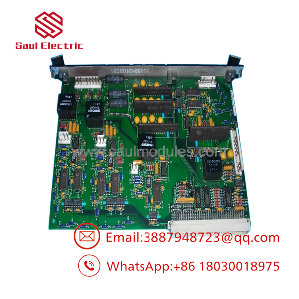
IS200SCNVG1ADC
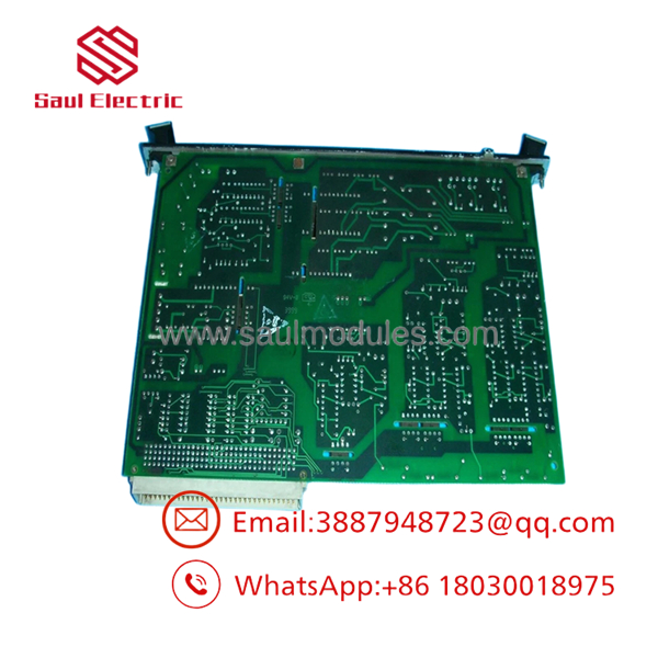
IS200SCNVG1ADC
Transparency SOP: QA & Testing
For this particular board, a generic “powers on” test is not enough.
1. Identification check
Verify IS200SCNVG1ADC, revision information, and board-family markings.
2. Physical inspection
Examine the PCB, P1 connector, six plug connectors, components, solder joints, and areas exposed to electrical or thermal stress.
3. Interface inspection
Pay particular attention to the connectors associated with current shunts, gate drivers, and DC-link circuits.
4. Electrical screening
Check for shorts, abnormal resistance paths, damaged semiconductors, and visible evidence of electrical overstress.
5. Functional testing
Where appropriate equipment exists, verify the gate-drive, sensing, feedback, and dynamic-braking interface functions under controlled conditions.
6. Final QA record
Document the actual board condition, revision, test procedure, results, traceability information, and warranty.
The board has four test points intended for development use, and the available technical description specifically warns that these points can carry high voltage and should not be accessed casually.
The Veteran’s Tech Trap Guide
⚠️ Trap #1 — This is a high-energy converter interface.
Do not treat the SCNV like a normal low-voltage Mark VI I/O card. Its interface circuitry is connected to power-converter functions, so isolation and discharge procedures must be followed.
⚠️ Trap #2 — Verify the rack position.
The IS200SCNVG1ADC is documented for Slot 6 and connection to J15 of the CABP backplane. A physically compatible location elsewhere does not prove correct application.
PRO TIP: Record every connector before removal. The six plug connections are associated with different converter-side circuits, so a wiring error can create a completely different fault after replacement.
⚠️ Trap #3 — Do not probe the development test points casually.
Available technical information identifies four test points and warns of high voltage. Use the applicable GE procedure and properly rated test equipment rather than probing them during energized operation.
⚠️ Trap #4 — A gate-drive fault may not originate on the SCNV.
Check the associated gate-driver and converter-side circuitry before condemning the PCB.
Dynamic FAQ
What is the GE IS200SCNVG1ADC?
The is a GE Mark VI SCR-Diode Converter Interface Board used in Innovation Series converter systems. It acts as a control-to-bridge interface.
What converter range is it designed for?
Available technical references identify it for 1000–1800 A stand-alone SCR-Diode converters in the Innovation Series.
How many SCRs can the board drive?
The board provides six-pulse sources and can drive three SCRs per board. It is not intended to drive the parallel SCRs from the same board configuration described in the documentation.
Where is the board installed?
The IS200SCNVG1ADC is documented for Slot 6 of the Innovation Series board rack and connects to J15 on the IS200CABP control assembly backplane.
What should I check before ordering a replacement?
Provide the complete part number, board revision, photographs of the actual PCB, rack position, and converter model/rating. Connector and board-revision information is particularly useful for compatibility verification.
How do I verify New Surplus authenticity and warranty?
Request photographs of the actual board and its identification label. Confirm whether it has ever been installed, repaired, modified, or functionally tested. Also obtain written warranty, DOA, and return terms. Do not treat “New Surplus” and “Refurbished” as equivalent conditions.



 Start Chat


