





Description
Key Technical Specifications
| Parameter | Value |
|---|---|
| Manufacturer | GE (General Electric) |
| Model | IS200TDBTH6ACD |
| Product Type | TMR Discrete I/O Terminal Board |
| Series | Mark VIe |
| Control Architecture | Triple Modular Redundancy (TMR) |
| Contact Inputs | 24 Group-Isolated Inputs |
| Relay Outputs | 12 Form-C Relays |
| Wetting Voltage | 100–145 V DC (H6 version) |
| I/O Pack Compatibility | Three PDIO I/O Packs |
| Communication | Ethernet via PDIO I/O Packs |
| Mounting | DIN Rail or Flat Panel |
| Terminal Blocks | Dual 48-point Terminal Blocks |
| Operating Application | Gas Turbine, Steam Turbine, Generator Control |
The IS200TDBTH6ACD is designed for GE Mark VIe TMR control systems. It supports three PDIO I/O packs and is not intended for operation with a single PDIO pack. Always verify hardware revision and system compatibility before installation.
Product Introduction
The GE IS200TDBTH6ACD is a Triple Modular Redundancy (TMR) Discrete I/O Terminal Board developed for the GE Mark VIe turbine control platform. It interfaces field contact inputs and relay outputs with the control system while maintaining the fault tolerance required for critical turbine applications.
The board supports 24 group-isolated contact inputs, 12 Form-C relay outputs, and three PDIO I/O Packs connected through dedicated D-type connectors. It is commonly deployed in gas turbines, steam turbines, and generator protection systems where continuous operation and redundant control are required.
Troubleshooting Quick Reference
| Symptom | Possible Cause | Relevance to this Part | Quick Check Method | Recommendation |
|---|---|---|---|---|
| Multiple input signals unavailable | Loss of wetting voltage | ✅ High | Measure external wetting voltage at JE1 connector | Restore field supply before replacing the board |
| Several relay outputs fail | Relay wiring or relay damage | ✅ High | Measure relay contacts and verify coil operation | Check relay circuits before replacing |
| Controller reports PDIO communication fault | PDIO I/O Pack or Ethernet issue | ✅ High | Verify PDIO LEDs and Ethernet connections | Inspect I/O Packs and network configuration |
| Random input state changes | Electrical noise or poor grounding | ⚠️ Medium | Inspect cable shielding and cabinet grounding | Correct grounding and cable routing |
| One TMR channel reports faults | Failed PDIO pack or connector | ✅ High | Swap with a known-good PDIO pack if permitted | Verify the I/O Pack before replacing the terminal board |
| Entire TMR I/O unavailable | Backplane or power distribution issue | ⚠️ Medium | Verify cabinet power and terminal connections | Check upstream power and rack hardware |
Field Tip: In Mark VIe TMR systems, the terminal board itself is less likely to fail than the associated PDIO I/O Packs, external wetting voltage supply, or field wiring. Before replacing the IS200TDBTH6ACD, record controller diagnostics, verify all three PDIO connections, and confirm the correct wetting voltage is present. This approach prevents unnecessary board replacements.
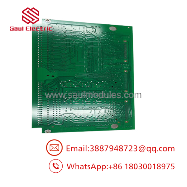
- IS200TDBTH6ACD
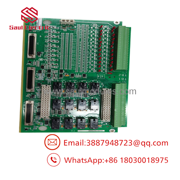
- IS200TDBTH6ACD
Frequently Asked Questions (FAQ)
Q1. What is the primary function of the ?
The provides the field termination point for discrete inputs and relay outputs in GE Mark VIe TMR systems. It interfaces field devices with three PDIO I/O Packs while maintaining redundant operation.
Q2. How many field signals does this board support?
The board supports 24 isolated contact inputs and 12 Form-C relay outputs. Optional relay expansion hardware can provide additional output capability.
Q3. Can the operate with only one PDIO I/O Pack?
No. The TMR version is designed to operate with three PDIO I/O Packs and is not intended for single-pack operation.
Q4. Is this module hot-swappable?
No. GE recommends shutting down the control cabinet, following lockout/tagout procedures, and using proper ESD protection before replacing the terminal board.
Q5. Is this product supplied as new or refurbished?
This listing refers to New Original (New Surplus) inventory unless otherwise specified. Each unit should undergo serial number verification, visual inspection, insulation checks, relay functional testing, and communication verification before shipment.
Q6. What testing should be completed before shipment?
A recommended quality inspection includes:
- OEM part number and serial number verification
- Visual inspection for corrosion, damaged terminals, or repair marks
- Contact input simulation
- Relay output functional testing
- PDIO connector inspection
- Insulation resistance verification
- Final ESD-safe packaging with QC documentation
Test reports and inspection photos should be available upon request.
Q7. What are the most common installation mistakes?
The most common issues include incorrect wetting voltage selection, wiring errors on the terminal blocks, improper cable shielding, and failing to reconnect all three PDIO I/O Packs. Before removing the old board, photograph every terminal connection and label field wiring. That simple step can eliminate hours of troubleshooting during commissioning.



 Start Chat


