





Description
Key Technical Specifications
| Parameter | Value / Specification |
| System Framework | GE Mark VI Speedtronic Control System |
| Board Identifier | Turbine Trip Requisition Board (TREG) |
| Revision / Configuration | H1B Baseline with DB Customization Layer |
| Control Redundancy | Formats signals for R, S, and T Triple Modular Redundant (TMR) paths |
| Solenoid Interfaces | Controls up to 3 Emergency Trip Mechanisms (ETMs) |
| Operational Voltages | Configurable for 24 VDC or 125 VDC solenoid loops |
| Input Channels | Mechanical trip/overspeed inputs, external trip interlocks |
| Diagnostic Monitors | Continuous loop current tracking, fuse status detection |
| Fusing Constraints | Individual overcurrent fuses for each solenoid feed circuit |
| Terminal Connections | Heavy-duty barrier block screw terminals for direct field wiring |
Product Introduction
The GE IS200TREGH1BDB serves as the primary hardware safety interface within the Mark VI Speedtronic control platform, directly orchestrating the turbine emergency shutdown sequence. It functions as the physical termination point where the controller’s safety logic commands the critical electro-hydraulic Emergency Trip Mechanisms (ETMs). By managing the vital interface between control logic and physical fuel or steam shutoff valves, it acts as a primary line of defense against destructive overspeed or thermal runaway conditions.
Engineered with high reliability in mind, the IS200TREGH1BDB supports a Triple Modular Redundant (TMR) hardware voting structure. The card accepts distinct trip signals from the R, S, and T control cores, running them through an onboard series-parallel relay array to implement 2-out-of-3 (2oo3) voting logic. This design ensures that a single failed component or corrupted sensor channel cannot cause an accidental, expensive nuisance trip, nor can it block a genuine emergency shutdown command when plant safety hangs in the balance.
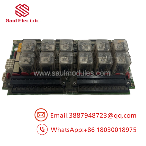
- IS200TREGH1BDB
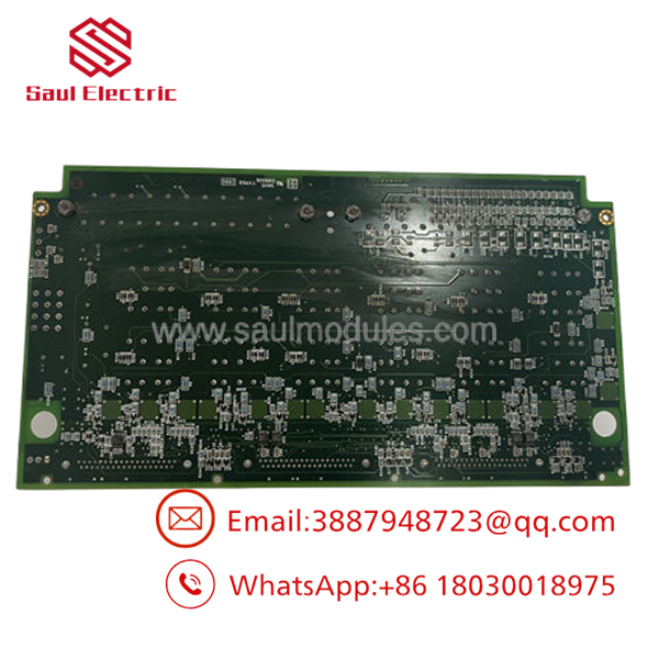
- IS200TREGH1BDB
Installation & Configuration Guide
Stage 1: Pre-Installation Preparation (Estimated Time: 20 minutes)
- ⚠️ Safety First: Replacing this card completely disables the active turbine emergency trip interlocks. Never attempt a swap while the turbine is online or on turning gear. Ensure the unit is completely shut down, isolated, and that all mechanical trip fluid systems are depressurized. Lock out and tag out (LOTO) all 125 VDC / 24 VDC control power sources and external breaker feeds connected to the TREG board.
- Tools Required: ESD wrist strap, calibrated torque screwdriver, medium slotted screwdriver, fine-tip wire markers, digital multimeter (DMM).
- Data Backup: Document the exact terminal layout of all field-side wiring loops. Take high-resolution photographs of the entire board face, ensuring all factory plug placements, jumper blocks, and visible hardware revisions are clearly readable.
Stage 2: Removing the Old Module (Estimated Time: 15 minutes)
- Fasten your grounded anti-static wrist strap to the enclosure frame before touching any electronics.
- Tag every single field wire landed on the barrier terminal blocks with its exact terminal designation (e.g., ETM1+, ETM1-).
- Carefully back out the terminal screws and remove the field wires. Inspect each wire for frayed copper strands or heat damage.
- Gently disconnect the internal ribbon routing cables (typically connecting to the VTUR or VPRO modules) by disengaging their plastic retaining clips.
- Unscrew the retention fasteners holding the TREG plate assembly to the control cabinet frame and pull the board straight out.
Stage 3: Installing the New Module (Estimated Time: 15 minutes)
- Unpack the new IS200TREGH1BDB inside an ESD-protected zone.
- Configuration Clone: Inspect the old card and the new card side-by-side. Carefully identify and duplicate the positioning of all hardware configuration jumpers (used to select between 24 VDC and 125 VDC solenoid voltage scaling, or to isolate specific monitor paths).
- Align the mounting chassis plate inside the Mark VI cabinet and tighten the fastening screws securely.
- Reattach the internal control-side ribbon cables, making sure the connector alignment keys index perfectly into the board slots.
- Land all field wires back into their documented terminal slots, securing them to the recommended torque specifications to avoid high-resistance points.
Stage 4: Power-On & Testing (Estimated Time: 25 minutes)
- Use your multimeter to verify that no ground faults exist on any of the field wire loops.
- Re-energize the primary and redundant control power breakers feeding the TREG rack.
- Observe the diagnostic LEDs on the module and cross-reference them with the master diagnostic logs in the GE Toolbox software application.
- Static Loop Test: Verify that the loop current monitors for ETM1, ETM2, and ETM3 report expected nominal standby values within Toolbox.
- Conduct a forced trip test via the software override matrix to verify that the TREG on-board relays click open and shut properly before introducing high-pressure hydraulics or fuel to the turbine deck.
Frequently Asked Questions (FAQ)
Can I hot-swap the IS200TREGH1BDB while the turbine is running?
No, the TREG board is a critical simplex termination block for the turbine’s emergency trip solenoids. Even though the upstream VPRO or VTUR control cores might operate in a redundant layout, pulling the physical TREG termination board immediately interrupts the active current loops holding the fuel/steam valves open. This will cause an immediate, unpreventable emergency shutdown of the turbine.
What do the specific “H1B” and “DB” parts of the model number signify?
The H1B indicates the underlying hardware revision level and circuit board architecture version established by GE. The trailing DB denotes a highly specific component configuration layer or factory-defined engineering modification (often indicating specific onboard component tolerances, specialized terminal layouts, or custom conformal coating parameters). For system compatibility, always match the full alphanumeric string whenever possible.
If my trip solenoids operate on 125 VDC, do I need a separate card variant?
The is designed to handle both 24 VDC and 125 VDC field solenoid configurations via internal hardware customization. However, you must carefully inspect and position the onboard configuration jumper links to select the correct system operating voltage before applying external power. Setting these jumpers incorrectly will result in diagnostic feedback faults or catastrophic damage to the monitoring circuitry.
Why does Toolbox register a “Solenoid Open Circuit” fault after swapping the board?
An open circuit diagnostic fault typically signals that a field wire is disconnected, a terminal block screw is loose, or an inline circuit protection fuse has blown. Check the physical onboard fuses on the TREG module with your multimeter. If the fuses are intact, inspect your terminal block connections to ensure all field conductors are making clean contact with the terminal pads.
Are these units brand new from GE factory assembly lines?
Because the legacy Mark VI platform has been largely succeeded by newer control solutions, these boards are sourced from New Original / New Surplus reserves. They represent un-deployed factory spare inventory acquired from industrial liquidations, warehouse overstock, or canceled construction projects, allowing you to secure genuine replacement components without the lead times of newer platforms.



 Start Chat


