





Description
Key Technical Specifications
| Parameter | Value |
| Manufacturer | General Electric (GE) |
| Part Number | IS200TREGH1BDC |
| Board Functional Acronym | TREG |
| Revision Level | H1BDC (Group 1, Backward Compatible Design Matrix) |
| System Voting Configuration | Triple Modular Redundant (TMR) 2-out-of-3 (2oo3) logic |
| Interface Connections | Multi-pin ribbon connectors for R, S, T control divisions |
| Trip Controls | Up to 3 independent mechanical hydraulic trip solenoids |
| Diagnostic Interfacing | Closed-loop contact feedback tracking for status telemetry |
| Mounting Orientation | Cabinet surface bracket mounting |
| Operating Temperature | 0 to +60°C |
Product Introduction
The GE IS200TREGH1BDC is a Turbine Emergency Trip Terminal Board (TREG) that functions as a core safety component within the Mark VI Speedtronic control ecosystem. This unit acts as the primary hardware interface between the electronic voting logic and the physical mechanical hydraulic trip solenoids responsible for isolating fuel or steam valves during an emergency shutdown (ESD).
Engineers rely on the IS200TREGH1BDC to carry out mission-critical 2-out-of-3 (2oo3) hardware voting logic. By splitting and voting diagnostic inputs across the R, S, and T channels, the board guarantees that if a single processor reports a false trip, operations continue safely. Conversely, a legitimate emergency signal will actuate the trip relays within milliseconds, removing power from the trip solenoids immediately.
Installation & Configuration Guide
Stage 1: Pre-Installation Preparation
- ⚠️ Safety First: The TREG board interfaces directly with turbine emergency trip circuits. A false step here will trip the unit or, worse, bypass a critical safety limit. Verify the turbine is completely offline, fully isolated, and that all hazardous hydraulic or pneumatic energy reserves are physically blocked. Lock out and tag out (LOTO) all 125 V DC solenoid power lines supplying the terminal matrix.
- Tools Required: Grounded ESD wrist strap, 3.5mm slotted screwdriver, digital multimeter, wire marker set, and a smartphone for terminal map captures.
- Data Backup: Document the exact positioning of all system ribbon connections routing to the primary I/O racks. Take clear photographs of the field terminal blocks to track the physical landing positions of the solenoid cables.
Stage 2: Removing the Old Module
- Connect the ESD wrist strap securely to the cabinet frame chassis.
- Carefully unplug the high-density communication ribbon cables from the onboard headers by clearing the integrated retaining latches.
- Systematically loosen the terminal screws and remove the field wiring bundles connected to the solenoid power loops. Label each wire immediately.
- Unscrew the chassis mounting hardware securing the board perimeter to the backplate sheet, then carefully lift the assembly out of the panel.
- ⚠️ Note: Verify the presence of any nylon isolation washers or grounding shims behind the screw tracks; keep these with the old board assembly.
Stage 3: Installing the New Module
- Keep the new IS200TREGH1BDC protected within its static shielding pouch until the mounting frame is fully clear of debris.
- Configuration Clone (Crucial): Compare the physical board layout, onboard link jumpers, and hardware revision suffixes against the unit you just pulled. You must match the physical configuration jumpers exactly to ensure proper voltage routing for the specific solenoid group installed at your facility.
- Position the card onto the cabinet bracket studs and tighten the mounting hardware to secure a definitive frame ground.
- Re-land the labeled field wires onto their correct terminal paths. Torque the barrier strip screws down to 7 in-lbs (0.8 Nm).
- Align and firmly push the system communication ribbon cables into the matching R, S, and T headers until the side clips lock completely.
- Self-Checklist:
- [ ] Jumpers and link options mirror the removed card layout perfectly.
- [ ] All ribbon cable retention mechanisms are snapped into place.
- [ ] Field terminals are securely locked down with zero loose strands.
Stage 4: Power-On & Testing
- Re-apply the internal cabinet low-voltage control power loop first, keeping the high-voltage trip solenoid circuit isolated if possible.
- Confirm the system software interface (ToolboxST) logs a clean board profile without triggering any configuration mismatch alarms.
- Check the feedback loop diagnostic statuses in the log. Execute a controlled diagnostic trip command via the software interface to verify that the onboard trip relays click and drop their outputs as expected.
- Re-energize the primary 125 V DC solenoid power supply loops and verify that the system maintains structural stability under a live simulated static trip test before initiating a turbine restart.
- ⚠️ Troubleshooting Note: If the system triggers an immediate open-loop fault code or fails to reset the trip latch, double-check that the jumpers are correctly configured for your specific configuration (Simplex vs. TMR setup) and audit the external loop limit switches.
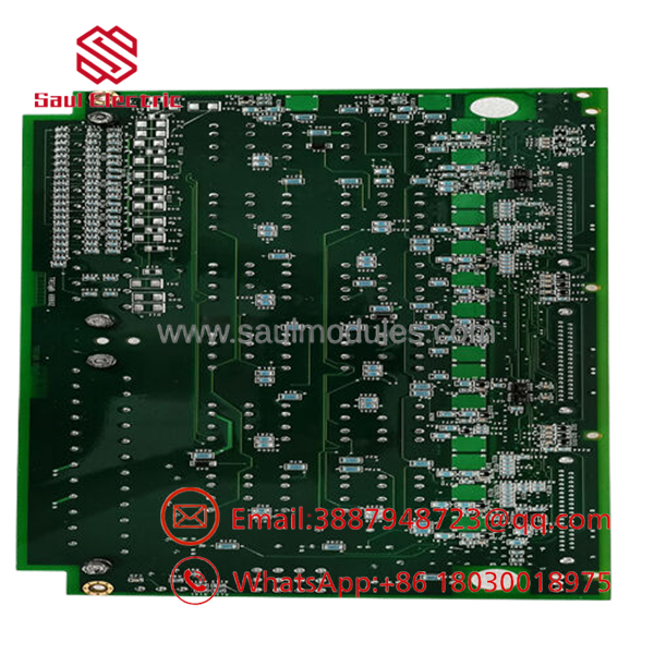
- IS200TREGH1BDC
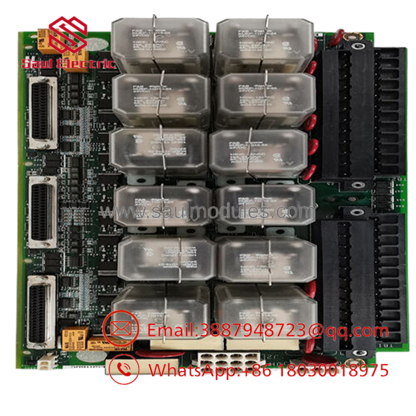
- IS200TREGH1BDC
Frequently Asked Questions (FAQ)
Can this TREG board be hot-swapped while the turbine is online?
No. Even though the Mark VI system features redundant control cores, the is the single, centralized physical meeting point for the emergency trip loops. Unplugging cable groups or severing terminal interfaces while the unit is operating will instantly break the continuous supervision loop. This drops the primary emergency solenoids, causing a complete and immediate mechanical turbine shutdown.
What is the mechanical role of the “BDC” suffix on this card?
The “BDC” designation tracks the hardware revision level, structural artwork modifications, and underlying component lifecycle updates implemented by General Electric. Boards featuring the “BDC” suffix preserve the foundational backward compatibility framework for Group 1 (H1) architectures, but they often incorporate upgraded relay form factors optimized to handle transient inductive back-EMF spikes from heavy solenoids.
Do I need to manually upload new logic files to this board after installation?
No software modifications or firmware uploads are required. The functions as a hardware routing and terminal protection card. It does not carry microprocessors or internal flash memories that retain program code. All processing instructions, logic configurations, and 2oo3 voting computations occur in the VTRX/TSVO I/O modules and core controllers.
What happens if the onboard trip relays fail? Can they be replaced individually?
While the relays are physical components mounted onto the board surface, executing component-level repairs inside a turbine safety system is generally not recommended by plant safety standards. If a relay contact welds shut or develops high internal contact resistance, the recommended practice is to replace the complete assembly to maintain OEM safety specifications.
Why choose a New Surplus unit over a factory repair cycle?
Procuring a New Surplus unit allows you to completely bypass extended OEM repair turnarounds and production lead times, which can sometimes stretch into several months. Our surplus modules are factory original, undergo complete visual, continuity, and functional verification checks, and are ready for immediate deployment to eliminate unexpected plant downtime.



 Start Chat


