





Description
Key Technical Specifications
| Parameter | Value |
| Board Type | Primary Turbine Trip Terminal Board (TRPG) |
| System Redundancy | TMR (Triple Modular Redundant) supporting R, S, and T control cores |
| Solenoid Voltage Rating | 24 V DC / 125 V DC nominal interface |
| Circuit Protection | Onboard fuses for active solenoid loop isolating lines |
| Relay Interfacing | Interlocked with VTUR / VPRO protection modules |
| Terminal Blocks | Multi-point barrier-type terminal strips for field connections |
| Sub-assembly Code | S1C5029 |
| Operating Temperature | −30 to +65 °C (−22 to 149 °F) environment rating |
Product Introduction
The GE IS200TRPGH1BDD, bearing the sub-assembly marker S1C5029, is a critical Primary Turbine Trip Terminal Board developed for the Mark VI Speedtronic control platform. This module functions as the final physical actuation barrier for emergency turbine protection loops, directly handling the high-current circuits that control fuel gas or liquid isolation stop-valves.
Designed for heavy-duty industrial gas and steam turbine systems, the “H1BDD” revision provides reliable hardware-level routing for Triple Modular Redundant (TMR) architectures. It voting-matches inputs from the R, S, and T control cores to guarantee that a false component trip signal won’t drop the entire system offline, while still ensuring an authorized Emergency Trip System (ETS) command shuts down fuel flow within milliseconds.
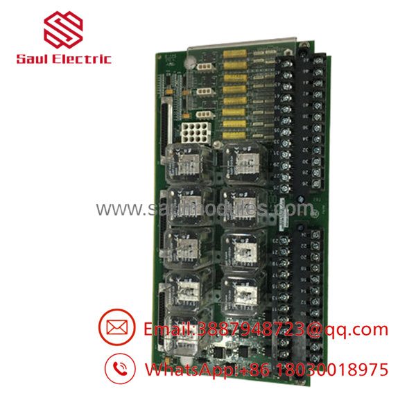
- IS200TRPGH1BDD S1C5029
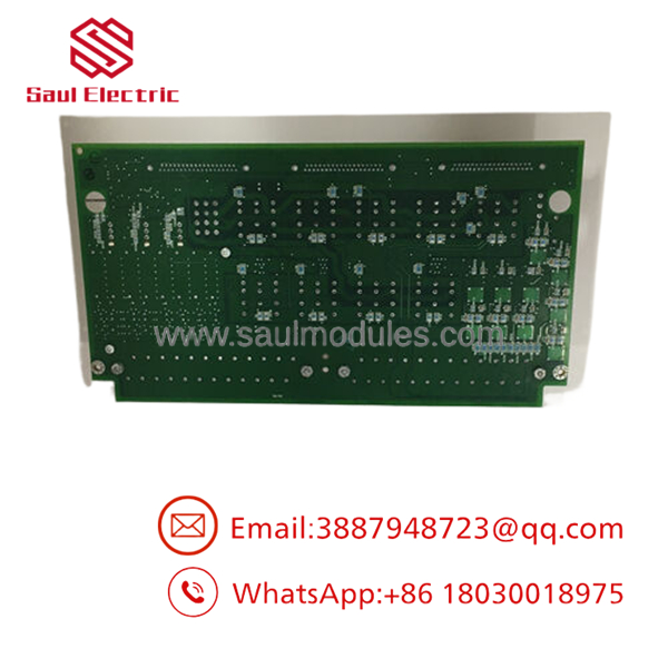
- IS200TRPGH1BDD S1C5029
Installation & Configuration Guide
Stage 1: Pre-Installation Preparation (Estimated Time: 15 minutes)
- ⚠️ Safety First: The TRPG board manages the main fuel isolation and trip solenoids. An unexpected trip signal during handling will drop the turbine instantly. The unit must be in a complete shutdown state with the hydraulic/pneumatic trip system depressurized and isolated. Lock out tag out all external 125 V DC solenoid power lines.
- Tools Required: Grounded ESD wrist strap, 3.5 mm slotted screwdriver, digital multimeter, wire marker kit, camera for wiring verification.
- Data Backup: Before pulling the existing board, pull the system diagnostics from the control software. Record any persistent diagnostic alarms tied to the VTUR/VPRO modules interface.
Stage 2: Removing the Old Module (Estimated Time: 15 minutes)
- Affix your ESD wrist strap and connect it to the metal framework of the control cabinet.
- Photograph all terminal landings to verify wire positions against the official schematic.
- Loosen terminal screws carefully. Disconnect and label every wire coming from the trip solenoids and external interlocks.
- Disconnect the system interface ribbon and multi-conductor cables linking the TRPG to the internal VME rack modules.
- Back out the mounting screws holding the PCB plate onto the sheet metal framing. Carefully slide the board out of the enclosure.
- ⚠️ Note: Check the back of the removed card for any scorch marks or blown trace paths, particularly around the high-current solenoid relay traces, to ensure the field device did not experience a dead short.
Stage 3: Installing the New Module (Estimated Time: 15 minutes)
- Keep the ESD wrist strap active. Unpack the new IS200TRPGH1BDD S1C5029 from its anti-static packaging.
- Check for onboard hardware fuses. Ensure all fuses on the new board match the current ratings specified by your turbine manual.
- Position the board onto the cabinet standoffs and tighten the mounting hardware down smoothly. Do not stress the substrate.
- Reland the labeled field wiring onto the terminal strips. Tighten connections firmly, checking that no stray wire braids span across terminals.
- Firmly seat the internal system interface cables back into their respective headers. Ensure the plastic retention clips click shut.
- Self-Checklist:
- [ ] Onboard fuses checked and verified correct.
- [ ] Field wire assignments match the pre-removal photographs exactly.
- [ ] Communication ribbons securely locked down.
Stage 4: Power-On & Testing (Estimated Time: 25 minutes)
- Pre-Power Check: Set your multimeter to continuity/resistance mode. Verify there are no ground faults on the field solenoid lines before introducing external power.
- Reapply power to the Mark VI control rack and re-energize the 125 V DC solenoid loops.
- Review the system software diagnostic logs. Verify that any “Board Disconnected” or “Trip Loop Open” faults clear out automatically.
- Execute a dry-run trip test via the software panel (with fuel lines still isolated/depressurized) to confirm that the relays on the TRPG board actuate as commanded by the R, S, and T cores.
- ⚠️ Troubleshooting Note: If the software triggers a “Solenoid Feedback Mismatch” alarm right away, verify that the active external voltage loop matches the expected feedback profile in your logic configuration file.
Frequently Asked Questions (FAQ)
Can I change out this TRPG board while the turbine is online?
No. This is an absolute line-stop operation. The IS200TRPGH1BDD carries the high-current loops that hold the primary fuel trip valves open. Pulling a wire, disconnecting a ribbon cable, or removing the board under power will open the trip circuit immediately. This forces the hydraulic fluid to vent, slamming the fuel valves shut and causing an immediate full-load turbine trip.
What does the “S1C5029” designation mean?
The code represents a specific sub-assembly production run or component BOM (Bill of Materials) variant for the IS200TRPGH1BDD base platform. When dealing with specialized protection hardware like the Mark VI TRPG board, certain sub-assembly footprints are built with specific relay component variants or internal trace weights to handle targeted current parameters. Always cross-verify this exact sub-assembly ID with your cabinet layout document.
Why does this board have separate interface lines for R, S, and T channels?
The Mark VI platform relies on a Triple Modular Redundant (TMR) safety architecture to avoid single points of failure. The TRPG board features a 2-out-of-3 (2oo3) hardware voting matrix layout for its trip relays. It takes distinct inputs from the R, S, and T control processors. If one core experiences a software fault or outputs an invalid trip command, the other two cores override it on the TRPG board, keeping the system running safely without an emergency shutdown.
What should I look for if the onboard fuses keep blowing after replacement?
If the fuses on the break immediately after power is applied, the issue is almost always a short circuit out in the field hardware, not an issue with the board itself. Use an insulation tester to check the external cables running to the trip solenoid valves, and check the internal resistance of the solenoid coils. A shorted coil will pull excessive current and blow the onboard protection fuses instantly.
Are older “H1B” or “H1BD” models directly interchangeable with this “H1BDD” unit?
While they belong to the same core TRPG hardware family, they are not always directly drop-in compatible due to physical component changes or trace updates denoted by the trailing “D” markers. An “H1BDD” variant contains updated noise suppression components designed to deal with inductive flyback from heavy-duty solenoids. Always review your system’s master configuration baseline in the software to confirm it accepts the updated “H1BDD” identifier before attempting a swap.



 Start Chat


