





Description
Key Technical Specifications
| Parameter | Value |
|---|---|
| Manufacturer | GE (General Electric) |
| Model | IS200TSVOH2B |
| Product Type | Turbine Servo Terminal Board |
| Series | Mark VI |
| Servo Channels | 4 bi-directional servo output channels |
| LVDT Inputs | Up to 6 valve position feedback inputs |
| Pulse Rate Inputs | 2 active pulse-rate inputs |
| Servo Output | Configurable bi-directional current output |
| Terminal Blocks | Two removable 24-terminal barrier strips |
| Maximum Field Wiring | Up to 12 AWG |
| Shielding | Chassis-ground shield termination strip |
| Board Technology | Surface-mount construction |
| Dimensions | Approximately 17.8 × 33.0 cm |
| Application | Gas turbines, steam turbines, generator control |
The IS200TSVOH2B interfaces electro-hydraulic servo valves, LVDT position sensors, and pulse-rate inputs with the Mark VI VSVO processor board. Current output ranges are jumper-selectable to match different servo valve coils. Always verify the hardware revision and jumper configuration before installation.
Product Introduction
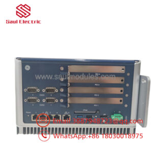
The GE IS200TSVOH2B is a Servo/LVDT Terminal Board developed for the GE Mark VI turbine control platform. It serves as the field interface between electro-hydraulic servo valves, LVDT position sensors, and the VSVO Servo Control Board, enabling accurate valve positioning for fuel, steam, and inlet guide vane control.
The board supports four servo control channels, six LVDT feedback inputs, and two pulse-rate inputs used for turbine flow measurement. Its removable terminal blocks, configurable servo current ranges, and integrated grounding arrangement simplify maintenance while providing dependable signal integrity in critical turbine control systems.
Troubleshooting Quick Reference
| Symptom | Possible Cause | Relevance to this Part | Quick Check Method | Recommendation |
|---|---|---|---|---|
| Servo valve does not respond | Open servo wiring or incorrect jumper setting | ✅ High | Measure servo coil resistance and verify jumper configuration | Correct wiring before replacing the board |
| LVDT feedback unstable | Faulty LVDT or damaged cable | ✅ High | Measure excitation voltage and inspect differential feedback signals | Verify the sensor before replacing TSVO |
| Turbine valve hunts or oscillates | Incorrect servo current range | ✅ High | Compare jumper settings with OEM documentation | Configure the proper current range |
| Controller reports LVDT fault | Open circuit or failed sensor | ⚠️ Medium | Measure LVDT continuity and excitation output | Replace the sensor if necessary |
| Pulse-rate input unavailable | Pickup sensor or wiring failure | ⚠️ Medium | Measure pulse signal amplitude at the input terminals | Inspect the magnetic pickup and field cable |
| Emergency trip remains active | External trip circuit energized | ✅ High | Verify JD1/JD2 trip wiring and Protection Module status | Clear trip condition before replacing hardware |
Field Tip: A TSVO board rarely fails without visible symptoms. Most field issues result from damaged LVDTs, incorrect jumper settings, failed servo coils, or poor field wiring. Before replacing the IS200TSVOH2B, record the existing jumper positions, photograph all terminal connections, and verify the servo coil resistance. These checks eliminate many unnecessary board replacements.
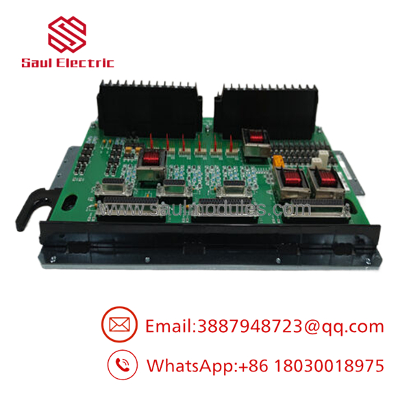
- IS200TSVOH2B
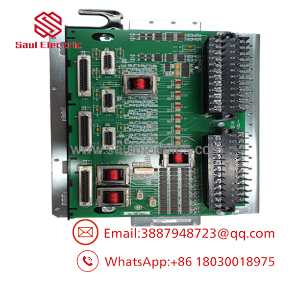
- IS200TSVOH2B
Frequently Asked Questions (FAQ)
Q1. What is the primary function of the ?
The connects electro-hydraulic servo valves and LVDT position sensors to the Mark VI VSVO Servo Control Board, allowing the controller to regulate turbine fuel, steam, or inlet guide vane position accurately.
Q2. How many servo channels does this board support?
The board supports four independent servo control channels, each providing bi-directional current output for electro-hydraulic servo valves.
Q3. How many LVDT inputs are available?
The accepts up to six LVDT valve position inputs. Depending on the application, one, two, three, or four LVDTs may be assigned to each servo control loop. When three sensors are used, the controller applies median voting for improved reliability.
Q4. Can this board be replaced while the turbine control cabinet is energized?
No. The board is not hot-swappable. Shut down the control system, follow lockout/tagout procedures, and use a grounded ESD wrist strap before removing or installing the board.
Q5. Is this product supplied as new or refurbished?
This listing refers to New Original (New Surplus) inventory unless otherwise specified. Each unit should complete visual inspection, electrical verification, connector inspection, and ESD-safe packaging before shipment.
Q6. What quality inspections should be completed before shipment?
A recommended inspection procedure includes:
- OEM part number and serial number verification
- Visual inspection for corrosion, repair marks, or damaged components
- Terminal block and connector inspection
- LVDT excitation verification
- Servo output functional testing
- Insulation resistance testing
- Final anti-static packaging with QC documentation
Test reports and inspection photographs should be available upon request.
Q7. What is the most common installation mistake?
The most frequent issue is changing the servo current jumper configuration or reconnecting the LVDT wiring incorrectly. Before removing the original board, photograph every terminal and record each jumper position. Reproducing the original configuration will prevent most commissioning delays and unnecessary turbine trips.


 Start Chat


