





Description
Key Technical Specifications
| Parameter | Value |
|---|---|
| Manufacturer | GE Energy |
| Model Number | IS200TVBAH2ACC |
| Product Type | Vibration Input Terminal Board |
| Platform | Mark VI Speedtronic Turbine Control System |
| Primary Function | Vibration signal termination and conditioning |
| Supported Sensors | Proximity probes and vibration transducers |
| Input Capacity | 8 vibration channels, 4 position channels, 1 Keyphasor input |
| Buffered Outputs | BNC, DB9, and DB25 interfaces |
| Probe Excitation | Approximately -24 V DC probe supply |
| Installation | Mark VI control cabinet |
| Operating Temperature | Industrial control environment |
| Application | Gas turbines, steam turbines, compressors, rotating machinery protection |
Product Introduction
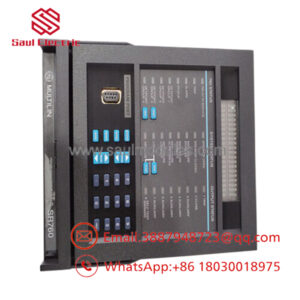
The GE IS200TVBAH2ACC is a Mark VI vibration input terminal board used in GE Speedtronic turbine control systems. It interfaces proximity probes, vibration sensors, and a Keyphasor reference signal with the turbine protection and monitoring system, providing accurate signal conditioning for machinery health monitoring.
The board is commonly installed in gas turbine, steam turbine, and compressor control cabinets where continuous shaft vibration monitoring is required. Before replacing the board, verify the probe type, terminal wiring, hardware revision, and associated Mark VI I/O module compatibility to prevent unnecessary commissioning work.
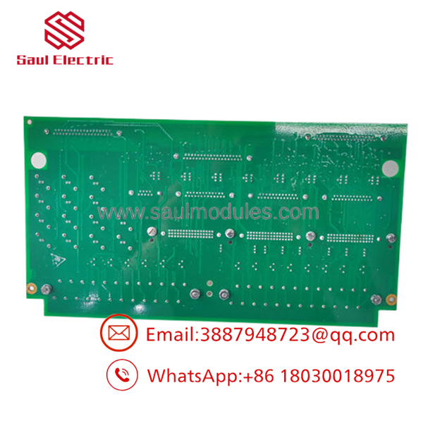
- IS200TVBAH2ACC
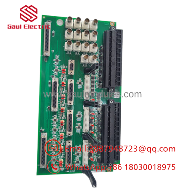
- IS200TVBAH2ACC
Troubleshooting Quick Reference
| Symptom | Possible Cause | Relevance to this Part | Quick Check Method | Recommendation |
|---|---|---|---|---|
| All vibration channels offline | Loss of probe power | ❌ Low | Measure probe supply voltage at the terminal board | Verify power before replacing the board |
| High vibration alarm on one channel | Failed proximity probe | ❌ Low | Substitute with a calibrated probe or use a signal simulator | Verify the sensor first |
| All channels show excessive noise | Shield grounding problem | ❌ Low | Inspect cable shielding and grounding method | Correct grounding before replacing hardware |
| No Keyphasor signal | Damaged probe or wiring | ✅ Medium | Measure Keyphasor waveform with an oscilloscope | Verify probe gap and wiring |
| Diagnostic alarm on vibration input | Interface circuitry fault | ✅ High | Review Mark VI diagnostics and inspect connectors | Replace the terminal board after confirming field devices |
| Intermittent vibration values | Loose terminal connection | ✅ Medium | Tighten all terminal screws and reseat connectors | Inspect wiring before replacing the board |
| Buffered outputs unavailable | Output connector damage | ✅ Medium | Measure buffered output using test equipment | Inspect connectors for mechanical damage |
Technical Note: Most turbine vibration faults originate from probe gap adjustment, damaged extension cables, grounding issues, or sensor failures. The IS200TVBAH2ACC terminal board is generally reliable and should only be replaced after these external causes have been eliminated.
Frequently Asked Questions (FAQ)
Q1. What is the IS200TVBAH2ACC used for?
The serves as the vibration signal interface for the GE Mark VI turbine control system. It connects vibration probes and Keyphasor sensors to the turbine protection hardware for continuous machinery monitoring.
Q2. Which sensors can this board support?
It supports eddy-current proximity probes, shaft position sensors, vibration probes, and a Keyphasor reference channel used for shaft speed and phase measurements.
Q3. Can I replace the board without changing configuration?
Usually yes.
However, document every field cable and connector before removal. Swapping vibration channels or the Keyphasor connection can generate false protection alarms during startup.
Q4. Is this board interchangeable with other Mark VI terminal boards?
No.
Although several Mark VI terminal boards appear physically similar, they perform different functions. Always match the complete part number and verify the installed hardware revision before ordering.
Q5. Why is New Surplus inventory less expensive than factory inventory?
Most New Surplus boards come from canceled turbine projects, OEM spare inventories, or unused maintenance stock. They have not been installed in service but are no longer part of standard OEM production.
Q6. What should I verify before ordering?
Verify:
- Exact model number ()
- Hardware revision
- Mark VI cabinet compatibility
- Probe type
- Terminal wiring
- Connector condition
- Associated vibration monitoring module
These checks help eliminate unnecessary downtime during replacement.
Q7. What warranty is typically available?
Most industrial automation suppliers provide a 12-month warranty on verified New Surplus or professionally tested boards. Request the inspection report, functional test documentation, and board photographs before shipment.
Quality Inspection & Testing SOP
1. Inbound Inspection & Traceability
- Verify GE identification labels, serial numbers, and hardware revision.
- Inspect the PCB for corrosion, damaged traces, cracked solder joints, bent connector pins, or repair evidence.
- Examine all terminal blocks and buffered output connectors.
- Record serial numbers for complete traceability.
2. Live Functional Testing
- Install the board in an in-house GE Mark VI test cabinet.
- Verify proper probe excitation voltage.
- Simulate proximity probe and Keyphasor inputs.
- Confirm buffered outputs and communication with the associated vibration monitoring electronics.
- Perform continuous operation for more than 24 hours while monitoring signal stability.
- Generate a documented functional test report.
- Test photos and videos are available upon request.
3. Electrical Parameter Testing
- Perform insulation resistance testing where applicable using a 500 V Megger.
- Verify protective ground continuity.
- Measure probe supply voltage and input signals using a calibrated Fluke 115 digital multimeter.
- Confirm stable operation throughout the burn-in test.
4. Firmware & Configuration Verification
- Verify hardware revision.
- Inspect connector integrity.
- Photograph the identification label before shipment.
- Document test configuration and inspection results.
5. Final QC & Packaging
- Final QC approval.
- Package the board in an ESD-safe bag.
- Protect with anti-static foam, bubble wrap, and a heavy-duty corrugated carton.
- Apply a dated QC Passed label.
Technical Pitfalls & Survival Guide
❗ Check Probe Gap Before Replacing the Board
I’ve seen vibration alarms disappear simply by correcting the probe gap.
Always verify probe clearance with the manufacturer’s specification before assuming the terminal board has failed.
❗ Label Every Cable
Eight vibration channels can become confusing during maintenance.
Take clear photographs and label every cable before disconnecting the original board. Reversed channels can create misleading machinery protection alarms.
❗ Verify Shield Grounding
Ground the cable shields exactly as specified by the turbine documentation.
Connecting both ends of the shield without approval can introduce electrical noise that looks like excessive shaft vibration.
❗ Inspect Extension Cables
Many intermittent vibration faults are caused by damaged extension cables rather than the terminal board itself.
Check cable continuity and connector condition before replacing hardware.
❗ Electrostatic Discharge (ESD)
Always wear a grounded wrist strap.
I once watched a technician replace a turbine interface board immediately after unpacking it without ESD protection. The board passed initial startup but later developed intermittent vibration channel faults that were difficult to reproduce.
Keep these checks in mind and you’ll eliminate most vibration monitoring problems, avoid unnecessary board replacements, and reduce turbine outage time.


 Start Chat


