





Description
Key Technical Specifications
| Parameter | Value |
|---|---|
| Functional Acronym | AEBI (Alternative Energy Bridge Interface Board) |
| System Compatibility | GE 1.5MW and 1.6MW Wind Turbine Generator (WTG) platforms |
| Control Series Platform | PACSystems Mark VIe Wind Control Architecture |
| OEM Cross-Reference Code | 104W5469P001 |
| Hardware Revision Rating | Revision H3B (Group 3, Functional Variation B) |
| PCB Environmental Treatment | Full factory-applied conformal coating for moisture and dust isolation |
| Nominal Operating Input | 24 V DC system power rail link |
| Operating Temperature | −30 to +65 °C (−22 to 149 °F) inside target nacelle cabinet |
| Storage Temperature Profile | −40 to +85 °C (−40 to 185 °F) |
| Approximate Dimensions | 17.8 cm × 5.1 cm × 30.5 cm (7.0 in × 2.0 in × 12.0 in) |
| Net Hardware Weight | 0.71 lbs (0.32 kg) |
Product Introduction
The GE IS210AEBIH3B is a specialized Alternative Energy Bridge Interface (AEBI) board developed by GE Energy for the PACSystems Mark VIe Wind Turbine Control architecture. Deployed extensively across global wind energy frameworks—most notably within GE 1.5MW and 1.6MW turbine asset fleets—this board is a vital communication and data link between core power converter bridges and the master turbine control processors.
Designed to operate reliably within high-vibration nacelle control boxes, the IS210AEBIH3B translates real-time signal loops to manage converter bridge dynamics. The card features a factory-applied conformal coating that protects sensitive surface-mount tracks against conductive carbon dust, salt air moisture, and localized condensation. This robust design guarantees deterministic execution of power distribution and sync logic under demanding grid and environmental conditions.
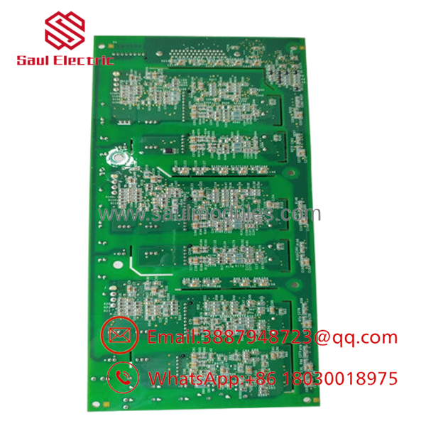
- IS210AEBIH3B
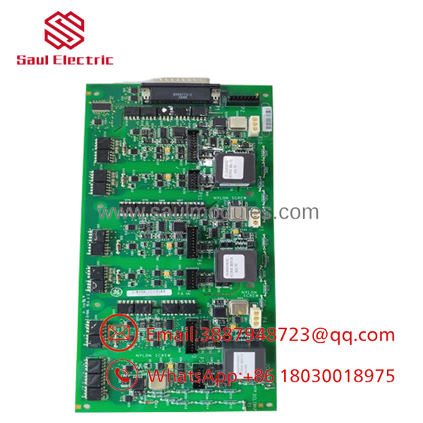
- IS210AEBIH3B
Installation & Field Swap Guide
Stage 1: Pre-Installation Preparation (Estimated Time: 15 minutes)
- ⚠️ Safety First: Lock out and tag out the primary input circuit breakers driving the converter control enclosure panel in the turbine tower or nacelle. Working around live bridge components carries significant electrical discharge risks and can cause tracking damage to new components.
- Tools Required: Grounded static-dissipative ESD wrist strap, small anti-static alignment screwdrivers, clean non-conductive safety pad, and a calibrated digital multimeter.
- Data Verification: Record your active turbine configuration parameters and any specific network node settings using your engineering terminal workspace before starting mechanical removal.
Stage 2: Removing the Defective Card (Estimated Time: 10 minutes)
- Affix your ESD wrist strap to a verified bare-metal enclosure grounding point.
- Label and carefully unplug all terminal wire links, power feeds, and communication ribbons mated to the front face of the board.
- Loosen the retention screws holding the PCB assembly to its mounting track or panel standoffs.
- ⚠️ Note: Pull the card straight outward from its seat smoothly. Do not rock or bend the board frame, as this can crack multi-layer trace pathways or damage neighboring interface components. Place the card immediately into an ESD shielding bag.
Stage 3: Installing the New AEBI Board (Estimated Time: 10 minutes)
- Extract the new IS210AEBIH3B card from its original anti-static box while positioned on your grounded workstation mat.
- Check that the hardware revision stamps, group ratings, and physical jumper configurations exactly mirror the board layout of the card being replaced.
- Position the board over the mounting slots, aligning it with the plastic tracks or nylon spacers. Press firmly near the connector pins to seat it flat.
- Hand-tighten the retention screws to establish a reliable chassis ground interface connection.
- Re-engage the keyed communication ribbon paths and securely snap down their side lock ears.
Stage 4: Power-On & Synchronization (Estimated Time: 15 minutes)
- Ensure the control cabinet is clear of loose tools, then re-energize the primary turbine control power circuit breaker.
- Verify with your multimeter that the incoming 24 V DC supply lines are stable at the terminal diagnostic check pads.
- Access the wind terminal control interface on your engineering monitor. Verify that the AEBI bridge card shows online, with zero communication timeouts or internal configuration mapping mismatches.
- ⚠️ Troubleshooting Note: If the software throws an immediate “Bridge Tracking Communication Error,” down-power the assembly and inspect the logic ribbon connections. Even minor debris or an improperly seated pin header will cause data drops and trigger immediate controller diagnostic faults.
Frequently Asked Questions (FAQ)
What specific purpose does the “AEBI” acronym represent in GE wind systems?
AEBI stands for Alternative Energy Bridge Interface. Within the Mark VIe wind turbine control architecture, this board acts as a high-speed communication link, interfacing data streams from power-generation converter bridges directly into the primary automation controller loops to maintain balanced output synchronization.
My original documentation lists a part number of 104W5469P001. Is this card interchangeable?
Yes. The number string 104W5469P001 is the underlying manufacturer engineering and component part number used directly by the factory production lines. It corresponds directly to the functional catalog number IS210AEBIH3B. They are the exact same component card and are fully interchangeable.
Why is conformal coating critical on the board variant?
Wind turbine nacelles and tower bases are subject to extreme environmental conditions, including rapid temperature swings, ambient condensation, coastal salt air, and conductive carbon dust from generator brush wear. The factory-applied conformal coating acts as a protective barrier, preventing these atmospheric hazards from bridging electronic traces and causing catastrophic short circuits.
Do I need to manually configure address switches or parameters on this board?
The board acts as an interface layer that processes data under the direction of the primary Mark VIe processor core. When executing a replacement swap, ensure any physical onboard jumper blocks match the position of the card being replaced. Once matched and powered, the master control application handles data routing based on your site hardware configuration file.
Since this legacy GE wind control asset is discontinued, what is the status of this item?
This component is available as New Original / New Surplus inventory sourced from climate-controlled wind utility spare parts pools, distributor overstock, and canceled infrastructure project reserves. Because factory production of these legacy generations has ceased, they are increasingly difficult to obtain. We run every unit through strict physical inspections and component continuity checks to ensure full out-of-the-box reliability, and back this card with our complete 1-year independent warranty.



 Start Chat


