





Description
Key Technical Specifications
| Parameter | Value / Specification |
| System Compatibility | GE Mark VIe Control System / ControlST Suite |
| Functional Application | Main Application Controller Card (MACC) / Converter Interface |
| Revision Tier | H1A Baseline with GG flavor assembly codes |
| Interface Card Pairing | Commonly docks with IS210BPPBH2BMD board profiles |
| Target Infrastructure | DFIG (Doubly-Fed Induction Generator) Wind Turbines & Steam/Gas assets |
| Network Capabilities | Dual or Triple Redundant real-time UDH / IONet Ethernet protocols |
| Processing Capacity | High-performance embedded DSP and microprocessor array |
| Diagnostic Metrics | Integrated bridge fault log, IGBT gate track faults, thermal alerts |
| Environmental Shielding | Industrial conformal coating against dust and humidity |
| Operating Ambient Temp | −30 to +65°C (−22 to +149°F) performance envelope |
Product Introduction
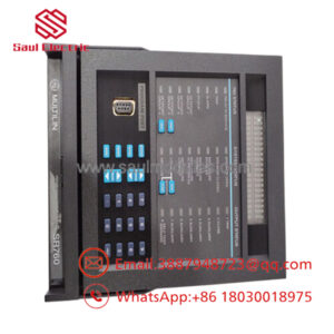
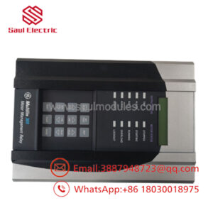
The GE IS210MACCH1AGG acts as the main algorithmic core within the GE Mark VIe control infrastructure, specifically tailored for Doubly-Fed Induction Generator (DFIG) wind energy applications and heavy-duty turbine subsystems. Operating as a Multi-Application Controller Card (MACC), this board functions as the primary real-time decision maker, managing complex electrical calculations required to safely throttle high-capacity power bridges. It processes dynamic variable inputs like rotor angle, stator voltage, and line frequencies to establish immediate control stability.
By managing the communication line to adjacent IGBT gate driver arrays, the IS210MACCH1AGG facilitates fast grid synchronization and limits structural harmonic resonance. It is engineered with precise processing limits, enabling millisecond-level adjustments to power factor vectors and reactive power injection targets. This direct response profile protects high-value generator parts against electrical back-feed loops during fast-moving grid grid disruptions.
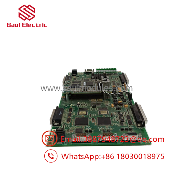
- IS210MACCH1AGG
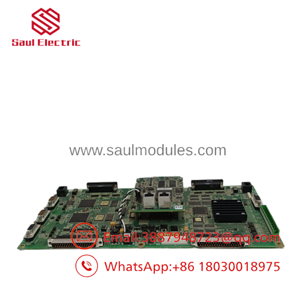
- IS210MACCH1AGG
Installation & Configuration Guide
Stage 1: Pre-Installation Preparation (Estimated Time: 15 minutes)
- ⚠️ Safety First: The MACC module actively dictates bridge firing coordinates. Never pull or install this card while the wind converter inverter cabinet or turbine system is live. Lock out and tag out (LOTO) all AC auxiliary power breakers and internal 24 VDC bus feeds. Verify with a multimeter that the internal DC-link capacitor banks have bled down to 0 V.
- Tools Required: Grounded static wrist strap, fine M3 slot screwdriver, hex alignment driver, ControlST software suite workstation.
- Data Backup: Connect through the local maintenance port using ControlST toolsets. Force a complete configuration and software parameter state upload from the current active processing stack. Archive this diagnostic profile file to local disk arrays.
Stage 2: Removing the Old Module (Estimated Time: 10 minutes)
- Affix your ESD grounding strap to a bare metal chassis bolt location on the frame matrix.
- Label and remove the specialized high-speed IONet Ethernet connections and neighboring fiber-optic patches.
- Loosen the retaining hardware bolts located at the corners of the card plate envelope.
- Carefully pull the IS210MACCH1AGG processor board forward, sliding it smoothly out from its guiding slots to preserve the integrity of the rear multi-pin interface pins on the background panel.
- Place the older assembly immediately into an static-shielded box.
Stage 3: Installing the New Module (Estimated Time: 15 minutes)
- Extract the new IS210MACCH1AGG from its sealed anti-static bag, keeping away from internal component surface pathways.
- Configuration Clone: Align the older board alongside your replacement unit. Verify that all option jumper arrays match exactly. If the replacement includes a modular daughtercard or interface base (like the BPPB board), check that the sub-component revision matches your target specifications.
- Gently slide the assembly card down the cabinet tracks until the rear socket pin connections engage tightly into the background frame slot.
- Hand-tighten the securing corner retention screws before applying final toolkit torque.
- Reconnect the labeled network strings and fiber channels.
Stage 4: Power-On & Testing (Estimated Time: 20 minutes)
- Restore the primary 24 VDC control power lines to the rack assembly. Leave the main inverter bridge power path disabled.
- Monitor the initial hardware LED codes: The power light should illuminate solid green, and the diagnostic network indicators should show high-frequency traffic.
- Establish communication with the module via the ControlST suite. Verify that the system path recognizes the module type and revision.
- Firmware Matching: Initiate a full configuration compile and flash download sequence to synchronize the local controller parameters with the validated master baseline code.
- Confirm that the diagnostic error log shows clear healthy parameters before returning the converter system to normal generation duties.
Frequently Asked Questions (FAQ)
Can this card be safely hot-swapped while the wind converter is grid-connected?
No. The is the core processing manager for the converter’s real-time switching loops. Pulling this processor card while online immediately interrupts the synchronized gate pulse patterns holding the converter bridges in line. This can result in localized overcurrent spikes, blown high-speed fuses, or permanent electrical destruction of the IGBT power stacks.
What do the trailing “GG” letters represent in the model identification code?
The GG suffix identifies a precise manufacturing design flavor configuration assigned by GE. This tier defines specific component characteristics, such as onboard memory chip tolerances, particular crystal oscillator clock speeds, or variations in the thickness of the defensive conformal coating applied to help the module withstand harsh ambient plant environments.
Why does my software throw an “IONet Connection Timeout” fault right after a swap?
An IONet connection timeout generally points to a physical network connection fault or a mismatched IP definition within your configuration tree. First, check that your network lines are seated in their proper ports (TX/RX lines can easily get swapped during a changeout). If the cables are correct, confirm that the module’s target IP addresses were initialized through ControlST during the flashing sequence.
Does this processor board directly store the turbine’s operating application program?
The volatile memory on the clears when control power is completely disconnected. The permanent application file resides within the non-volatile storage chip, but the active operational logic parameters should always be updated and verified by running a configuration download sequence from the engineering workstation using ControlST after a board replacement.
Can I run this module without its associated interface board?
No, the processor relies on an adjacent interface baseboard configuration (such as the IS210BPPB module) to route physical signal inputs and translate low-level diagnostic feedback lines. Operating the processor card without its structural interface layer leaves it isolated from the system’s fiber-optic paths and I/O tracking loops.

 Start Chat


