





Description
Key Technical Specifications
| Parameter | Value |
|---|---|
| Manufacturer | General Electric (GE) |
| Part Number | IS215UCVEH2AE |
| Functional Acronym | UCVE |
| Revision Level | H2AE (Group 2, High-Performance Production Matrix) |
| Processor Type | 300 MHz Intel Celeron |
| Memory Configuration | Onboard SDRAM and flash-based non-volatile storage |
| Interface Ports | 10/100M Ethernet (RJ-45), COM1/COM2 Serial (RS-232/485) |
| Bus Interface | Standard VME64 backplane architecture |
| System Configurations | Simplex, Dual, or Triple Modular Redundant (TMR) setups |
| Operating Temperature | 0 to +60°C |
Product Introduction
The GE IS215UCVEH2AE is a single-slot VME Controller Board (UCVE) that serves as the primary computational hub for the Mark VI Speedtronic turbine control and EX2100 excitation systems. Driven by an onboard 300 MHz processor, this master card executes critical turbine governing algorithms, tracks analog and discrete I/O, and manages real-time sequencing for heavy utility assets.
Equipped with high-density Ethernet and serial communication interfaces, the IS215UCVEH2AE establishes deterministic data transfers between the controller rack and the localized human-machine interface (HMI). Its specialized Group 2 “H2AE” design profile delivers stable clock cycles and enhanced memory handling, allowing it to seamlessly run within Triple Modular Redundant (TMR) arrays without risking synchronization loss.
Installation & Configuration Guide
Stage 1: Pre-Installation Preparation
- ⚠️ Safety First: The UCVE card handles core processing for live turbine infrastructure. Swapping this board while the turbine is online can cause un-trippable conditions or an unscheduled plant shutdown. Ensure the machine is offline and fully isolated. Turn off power to the target VME rack division. Use a multimeter to confirm the backplane power supply rails are completely dead before proceeding.
- Tools Required: Grounded anti-static (ESD) wrist strap, static-shielding mat, flathead screwdriver, and an Ethernet crossover cable.
- Data Backup: Open the Toolbox software application. Perform a complete backup of the existing application code, network parameters, IP configurations, and system topology maps assigned to this specific controller node.
Stage 2: Removing the Old Module
- Securely attach your grounded ESD wrist strap to a bare metal point on the control rack chassis.
- Label and carefully disconnect all front-panel communication cables, including Ethernet lines and serial connectors.
- Loosen the upper and lower captive mounting screws integrated into the card faceplate.
- Rotate the upper and lower ejector tabs outward simultaneously to disengage the board from the high-density VME backplane pins, then slide the module out of its guide tracks.
- ⚠️ Note: Immediately slide the pulled card into an ESD protective bag. Do not place it on ungrounded surfaces or expose the onboard circuit components to dust.
Stage 3: Installing the New Module
- Unpack the new IS215UCVEH2AE module only when you are within an ESD-safe workspace.
- Configuration Clone (Crucial): Visually match the physical hardware configuration, layout, and flash card positioning of the new board against the original card. Ensure any onboard memory cards or hardware jumpers match your system drawing specifications exactly.
- Align the card edge with the plastic upper and lower slot tracking guides within the VME rack. Slide the module slowly inward until the rear pins make contact with the backplane.
- Firmly push both ejector handles inward until they lock flat against the faceplate, seating the card into the backplane connectors. Tighten the top and bottom captive screws.
- Securely reattach all front-panel communication cables to their corresponding ports.
- Self-Checklist:
- [ ] Front-panel ejector tabs are fully latched and card is flush in the rack.
- [ ] Captive chassis screws are tight to establish a solid frame ground interface.
- [ ] Network and serial interface cables are connected back to their original ports.
Stage 4: Power-On & Testing
- Restore control power to the specific VME processor rack division.
- Monitor the front-panel status LEDs during the boot sequence: the RUN LED should stabilize into its normal state, and the FAIL indicator must remain dark.
- Establish a connection via the Toolbox environment. Ping the target IP address to verify active network communication with the new board.
- Re-download the validated application logic baseline and network configurations to the controller. Perform a cold reboot to ensure the memory allocations initialize correctly.
- ⚠️ Troubleshooting Note: If the FAIL LED lights up solid red or a
SYS_BOOT_ERRcode appears in your system diagnostic logs, check for a firmware mismatch or a loose flash memory assembly on the board.
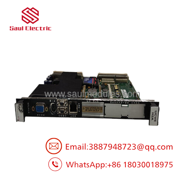
- IS215UCVEH2AE
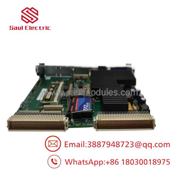
- IS215UCVEH2AE
Frequently Asked Questions (FAQ)
Can I hot-swap this processing board while the turbine is running?
No. The functions as the main processor for the control system. Even in a Triple Modular Redundant (TMR) network architecture, pulling a primary controller board while the system is under load introduces severe risks of communication lag or voting mismatch alarms across the remaining divisions. Always isolate power to the individual rack division before performing a replacement.
What is the explicit role of the “H2AE” revision suffix?
The “H2AE” designation specifies the exact product group and manufacturing revision baseline. The “H2” identifies it as part of the Group 2 hardware matrix, which utilizes distinct clock speeds and memory maps compared to older Group 1 (H1) modules. Matching this exact suffix prevents backplane bus communication errors and compilation issues during software downloads.
Do I need to re-flash the firmware or operating system when installing this board?
The core runtime environment and system configuration parameters are stored within non-volatile flash memory. When installing a New Surplus unit, you must verify that the underlying baseline firmware version loaded on the controller matches the software version defined in your plant’s active Toolbox configuration. If a mismatch occurs, use the Toolbox utility to download the correct firmware package before loading your application logic.
Why are the diagnostic LEDs flashing amber during my initial startup?
An amber or yellow status indication during initial bootup typically indicates that the processing unit is executing its power-on self-test (POST) routines or waiting for a valid application image download from the master workstation. If the amber indicators persist for more than five minutes, check the network parameters to ensure the board is not stuck in a boot-loop caused by a missing IP address assignment.
How do you test and verify the integrity of these legacy processing cards?
Every module undergoes a rigorous multi-stage quality control process. We conduct visual structural inspections, anti-counterfeit checks, and power-on boot tests. Following this, the board is installed into a live VME test rack to verify real-time data execution, backplane throughput, and communications port response under load profiles before it is packed for shipment.


 Start Chat


