





Description
Key Technical Specifications
| Parameter | Value |
| Manufacturer | General Electric (GE) |
| Part Number | IS215UCVEM09B |
| Functional Acronym | UCVEM / UCVE |
| Operating System | QNX Real-Time Multitasking OS |
| Processor Speed | 300 MHz Intel Celeron |
| Base Hardware Configuration | Combined IS215UCVEH2A baseboard + TPMC815-11 ARCNET mezzanine card |
| Execution Rate | Up to 100,000 rungs or blocks per second |
| Communication Interfaces | 10BaseT/100BaseTX RJ-45 Ethernet, Isolated ARCNET (2.5 Mbps via COM20020), COM1 & COM2 RS-232C |
| Power Consumption | +5 V DC @ 6.6 A (Typical) / 8.6 A (Max); ±12 V DC @ 180 mA (Typical) |
| Peripheral Ports | VGA Monitor port, PS/2 Keyboard/Mouse port |
| Form Factor | Single-slot, 6U high Versa Modular Eurocard (VME) standard |
Product Introduction
The GE IS215UCVEM09B is a single-slot, 6U high VME Controller Card configured as a Single Board Computer (SBC) for General Electric Mark VI Speedtronic turbine control systems. Specifically deployed in land-marine aero-derivative (LM) setups, balance of plant (BOP), and Load Commutated Inverter (LCI) static starter configurations, this card runs a high-speed QNX real-time multitasking operating system to achieve deterministic processing loops.
Structurally, the IS215UCVEM09B integrates an IS215UCVEH2A host processor card with a factory-installed TPMC815-11 PCI Mezzanine Card (PMC) daughterboard. This architecture provides the module with a dedicated, isolated hybrid ARCNET interface running at 2.5 Mbps alongside multi-subnet Ethernet infrastructure. This configuration allows for high-throughput data synchronization between the control system database (CSDB) and peripheral I/O modules via the common VMEbus backplane layout.
Installation & Configuration Guide
Stage 1: Pre-Installation Preparation
- ⚠️ Safety First: Modifying or replacing a primary VME rack controller poses substantial operational risks. Ensure the turbine or LCI starter bank is entirely shut down, isolated from active utility lines, and locked out/tagged out (LOTO). Isolate auxiliary power feeds going into the targeted VME rack. Use a digital multimeter to confirm all internal power distribution rails are dead before extracting hardware.
- Tools Required: Grounded anti-static (ESD) wrist strap, static-shielding mat, small flathead screwdriver, and an Ethernet crossover cable.
- Data Backup: Launch the GE Control System Toolbox application. Perform a full backup of the existing application logic, active block libraries, tuning parameters, IP network configurations, and logical subnet masks assigned to the controller division.
Stage 2: Removing the Old Module
- Securely attach your grounded ESD wrist strap to the grounding point on the VME rack rack-ear.
- Label and carefully detach all front-panel cabling: Ethernet lines, the ARCNET drop cable, RS-232C lines, and any attached keyboard/VGA peripherals.
- Loosen the upper and lower captive mounting screws integrated into the card faceplate.
- Grip the upper and lower ejector handles, rotate them outward simultaneously to unseat the high-density DIN connectors from the VME backplane pins, and pull the board straight out along the chassis tracking tracks.
- ⚠️ Note: Immediately slide the pulled card into a static-shielding pouch. Do not expose the onboard PMC daughterboard assembly or open traces to ambient warehouse dust.
Stage 3: Installing the New Module
- Keep the new IS215UCVEM09B inside its static-safe packaging until the exact moment of physical rack insertion.
- Configuration Clone (Crucial): Cross-check the board label identifiers. Visually verify that the mezzanine card on the replacement layout matches the original TPMC815-11 configuration. Match any manual hardware jumpers or DIP switches located on the host card body exactly to define proper node addressing and energy routing.
- Align the card edge boundaries with the upper and lower slot tracking channels within the rack matrix. Slide the module slowly inward until the rear pins seat loosely against the backplane.
- Press both ejector levers inward firmly and simultaneously until they click flat against the faceplate, drawing the board fully flush into the backplane matrix. Lock down the top and bottom captive screws.
- Reconnect all front-panel communication cables to their corresponding ports.
- Self-Checklist:
- [ ] Front-panel ejector tabs are fully latched and card faceplate is flush in the rack.
- [ ] Captive screws are tightened down completely to maintain a solid frame ground interface.
- [ ] Network, ARCNET, and serial cables are returned to their designated ports.
Stage 4: Power-On & Testing
- Re-apply low-voltage control power to the specific VME processor rack assembly.
- Observe the front-panel status LEDs during initialization: the Power Status indicator must light up, the flash activity light will flicker, and the VMEbus SYSFAIL indicator must clear (turn off) once the QNX OS completes its boot phase.
- Open the Toolbox diagnostic environment, establish communication via the primary Ethernet port, and ping the assigned IP address to check online status.
- Download the validated application logic configuration baseline and logical subnet parameters to the controller. Perform a cold reboot to ensure the memory allocations stabilize cleanly.
- ⚠️ Troubleshooting Note: If the SYSFAIL LED remains illuminated red after the initialization window, an internal hardware failure or a structural PMC mezzanine mapping conflict exists. Disconnect power and check for a loose daughterboard mounting screw or an improper jumper profile.
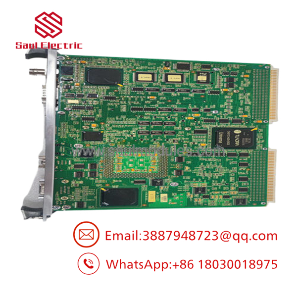
- IS215UCVEM09B
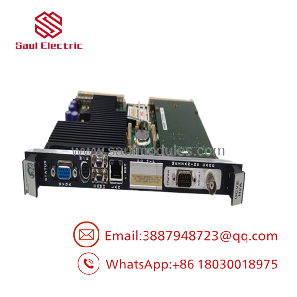
- IS215UCVEM09B
Frequently Asked Questions (FAQ)
Can I hot-swap this controller card while the control system is live?
No. The houses the primary single-board computer running the QNX operating system. Extracting this board while the VME backplane is energized will disrupt data synchronization across the Control System Database (CSDB), crash the local VMEbus communication lines, and cause an immediate emergency trip of the managed turbine or LCI starter package. Always isolate power to the individual rack division before performing a replacement.
What is the purpose of the integrated TPMC815 PMC daughterboard?
The TPMC815 is a standard PCI Mezzanine Card (PMC) interface module attached directly to the baseboard. It provides a dedicated ARCNET network interface driven by a COM20020 controller. This allows the to participate in legacy ARCNET local area networks (supporting Star, Tree, or Bus topologies up to 2.5 Mbps) while isolating sensitive control processing from line surges through an isolated hybrid interface.
Does this board store the application runtime logic permanently?
The board stores the runtime configuration and operating files in onboard non-volatile flash memory. However, when putting a New Surplus unit into operation, you must re-download your plant’s specific application block architecture and baseline network profiles from the master engineering workstation using the Toolbox utility. The card will validate its toolbox configuration against existing rack hardware at every power-up cycle.
Why is a separate logical subnet address required for the secondary Ethernet port?
The UCVEMxx family of modules supports advanced multi-subnet routing. The secondary Ethernet interface allows the card to communicate concurrently on a distinct, isolated IP network segment (such as a localized Modbus slave infrastructure or data historian network) without introducing cross-talk, network lag, or packet collision risks onto the primary EGD (Ethernet Global Data) highway.
How do you verify the functionality of these complex mezzanine card assemblies?
Every module undergoes rigorous quality control processing. We conduct high-definition visual trace audits, anti-counterfeit screening, and independent component testing on both the host card and the PMC daughterboard. The integrated assembly is then mounted in a live VME test rack running the QNX real-time operating system to test backplane throughput, ARCNET communication cycles, and Ethernet data transfers under simulated operational loads before shipment.





 Start Chat


