





Description
Key Technical Specifications
| Parameter | Value / Specification |
| System Architecture | GE Mark VIe Distributed Control System (DCS) |
| Functional Acronym | PDOA (Discrete Output Application Pack) |
| Catalog / Part Number | IS220PDOAH1A / 336A4940CSP2 |
| Hardware Variant | H1A Baseline Revision |
| Processor Module | Dual-core high-speed embedded microcontroller array |
| Output Capacity | Drives up to 24 discrete output circuits via matching terminal block |
| Network Redundancy | Dual-channel 100Base-TX IONet interfaces (RJ45 connectors) |
| Input Power Requirements | 28 VDC nominal voltage window (18 VDC to 32 VDC range) |
| Hardware Fusing | Onboard surface-mounted electronic overcurrent fuses |
| Diagnostic Monitors | Loop voltage validation, output contact feedback, temperature sensing |
| Operating Ambient Temp | −30 to +65°C (−22 to +149°F) structural operating window |
Product Introduction
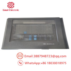
The GE IS220PDOAH1A, identified by engineering manufacturing code 336A4940CSP2, is a high-density Discrete Output (PDOA) I/O pack developed for the GE Mark VIe control architecture. This compact, ruggedized processing node mounts directly onto compatible discrete terminal boards (such as the TDOA or TRLY series), converting high-speed digital application logic into physical output states. It is engineered to operate load networks including solenoid valves, status lamps, interlock circuits, and auxiliary master control relays.
Equipped with dual 100 Mbps Ethernet RJ45 network links, the IS220PDOAH1A communicates natively across the internal real-time IONet framework. The pack contains localized processing hardware that executes continuous point-level diagnostic checks, including loop voltage feedback and terminal track monitoring. This constant tracking allows the module to verify that an external circuit is complete and ready to actuate before a control command is sent, increasing system safety and reducing troubleshooting times.
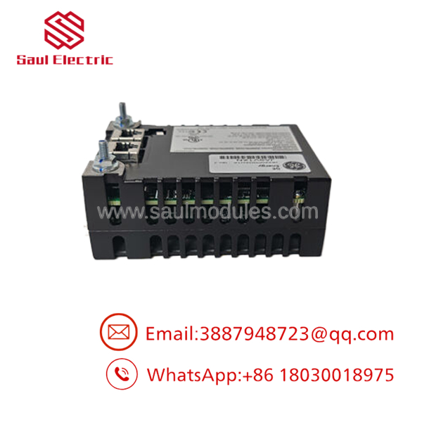
- IS220PDOAH1A 336A4940CSP2
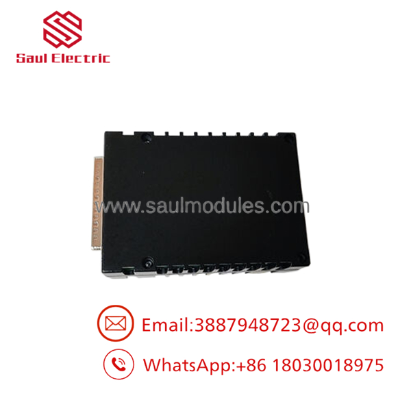
- IS220PDOAH1A 336A4940CSP2
Installation & Configuration Guide
Stage 1: Pre-Installation Preparation (Estimated Time: 10 minutes)
- ⚠️ Safety First: The PDOA pack controls high-power digital outputs that can immediately activate field machinery. Never swap an active output module while the turbine or plant automation process is running online. Confirm that all control elements are switched to a safe manual lockout or maintenance sequence, and execute a full lock out/tag out (LOTO) on the 28 VDC power distribution bus feeding the target I/O base.
- Tools Required: Grounded static prevention wrist strap, medium flathead screwdriver, laptop loaded with the relevant ControlST software suite configuration.
- Data Backup: Open ToolboxST on your engineering workstation and upload the current parameter assignments for the specific rack segment. Take note of the electronic ID (barcode string) and the IONet network IP coordinates mapped to this physical node position.
Stage 2: Removing the Old Module (Estimated Time: 5 minutes)
- Affix your anti-static wrist strap to a verified structural grounding point on the enclosure frame.
- Carefully unplug the dual IONet Ethernet cables connected to the top RJ45 network ports. Tag the network strings to ensure they are reconnected to the correct primary and secondary ports (IONet A / IONet B).
- Loosen the two heavy-duty jack screws on the front face of the PDOA module casing using a flathead screwdriver.
- Pull the module straight out from the terminal board connector pins.
- ⚠️ Note: Inspect the underlying terminal board connector pins to ensure they are straight and free of carbon tracking or debris before attempting to mount the replacement unit.
Stage 3: Installing the New Module (Estimated Time: 10 minutes)
- Extract the new IS220PDOAH1A (336A4940CSP2) pack from its anti-static packaging.
- Align the rear terminal slot of the PDOA pack with the physical alignment pins on the terminal board tracking base.
- Push the module firmly onto the board seat until the internal multi-pin socket connects tightly with the backplane header pins.
- Alternating between the two jack screws, tighten them evenly by hand to pull the module flush and secure it to the base plate. Avoid over-tightening to protect the internal plastic housing.
- Reconnect the primary and secondary IONet Ethernet patch lines to their matching RJ45 ports.
Stage 4: Power-On & Testing (Estimated Time: 15 minutes)
- Restore the 28 VDC control power supply to the I/O rack.
- Watch the physical LED status indicators on the module faceplate:
- Power should display a solid green light.
- Online should light up green once network handshakes are established.
- ⚠️ Troubleshooting: If the Fault LED illuminates solid amber or red, check the error logs in ToolboxST for an electronic ID mismatch or a firmware version conflict.
- Open ToolboxST to initiate an online configuration synchronization scan. If the system prompts a hardware mismatch notification, update the Electronic ID parameter with the new barcode string and push the configuration download to the controller.
- Perform an offline channel test by manually pulsing the discrete relays from the software terminal matrix to confirm execution before restarting automated process systems.
Frequently Asked Questions (FAQ)
Can this module be hot-swapped while the terminal board is powered?
In an active Triple Modular Redundant (TMR) control framework using multiple parallel I/O packs on a shared terminal board, you can hot-swap a single failed pack while the system is powered. However, this must only be attempted if your system logic is explicitly configured for TMR voting and the remaining redundant packs are functioning correctly. For simplex or non-redundant system loops, pulling the pack will immediately drop all output states, which can cause a plant trip.
What is the relationship between code and part number 336A4940CSP2?
The designator is the official GE marketing and ordering catalog number, which tells you the functional family (PDOA), hardware revision tier (H1A), and platform class (IS220 pack). The string 336A4940CSP2 represents the precise manufacturing internal bill-of-materials, layout tracking index, and firmware baseline component mapping applied during factory production. Both numbers must align to ensure exact component parity.
Why does the module display a “Firmware Mismatch” fault inside ToolboxST after a changeout?
This warning indicates that the embedded operating system software flashed onto the new replacement module is different from the master software baseline configured in your project’s ControlST environment. To resolve this, connect to the module via ToolboxST, put the node into configuration mode, and select the “Update Firmware” command to upload the correct project firmware version onto the pack.
Does this I/O pack directly handle high-voltage AC load currents?
No, the is a low-voltage logic processing module that runs on a 28 VDC control power rail. It does not route high-voltage field current through its internal circuit board traces. Instead, it sends low-current command pulses down to heavy-duty dry contact relays or interposing terminal arrays (like a TRLY block) mounted on the adjacent base terminal assembly, which handle the high-voltage field loads.
How does the module handle loop diagnostics for open field circuits?
The PDOA pack features built-in voltage monitor channels that continuously measure trickling current across the output terminals, even when the command state is opened or turned off. If an external field solenoid coil opens, an inline circuit fuse clears, or a field wire is cut, the voltage monitoring circuit detects the lack of continuity and flags an open loop diagnostic alarm in the centralized engineering log.


 Start Chat


