





Description
Key Technical Specifications
| Parameter | Value |
|---|---|
| Processor Architecture | AMD Quad-Core running at 1.2 GHz internal clock speed |
| System Memory | 2 GB volatile DDR3 SDRAM memory block |
| Internal Storage | 2 GB internal solid-state NAND flash drive (holds configuration & logs) |
| Operating System Engine | Embedded, deterministic QNX real-time operating system (RTOS) |
| Total Ethernet Interface Ports | 4 x 10/100/1000 Mbps RJ45 ports (3 x Dedicated IONet, 1 x Corporate/Plant link) |
| Redundancy Configurations | Natively supports Simplex, Dual (Hot-Standby), and Triple Modular Redundant (TMR) loops |
| Local Programming Interface | 1 x Front-panel RS-232 serial diagnostic port (RJ-45 connector geometry) |
| Power Supply Input Requirements | Nominal 28 V DC (Operating voltage envelope: 18 to 32 V DC; 1.5 A max) |
| Local Status Matrix | 8-Segment alpha-numeric LED diagnostic display + 4 x Status indicators |
| Enclosure Protection Class | IP20 / NEMA Type 1 industrial housing layout |
| Ambient Temperature Limits | −30 to +65 °C (−22 to 149 °F) structural operating range |
Product Introduction
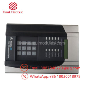
The GE IS420UCSBH4A is a high-performance, single-slot Programmable Automation Controller (PAC) engineered as the main computational engine for General Electric’s PACSystems Mark VIe and Mark VIeS control platforms. Powered by an industrial 1.2 GHz AMD Quad-Core processor and running a deterministic real-time QNX operating system, this module is built to execute complex, high-speed control logic for large-scale gas and steam turbines, balance-of-plant automation, and critical safety-instrumented systems.
Unlike traditional rack-mounted CPUs, the UCSBH4A is a standalone controller that mounts directly inside the panel chassis and interfaces with distributed I/O packs over high-speed Ethernet loops. It features four built-in Gigabit Ethernet ports, with three dedicated to GE’s proprietary, deterministic IONet fabric for real-time I/O data distribution, and one isolated port for connection to the corporate plant network or local HMI workstations.
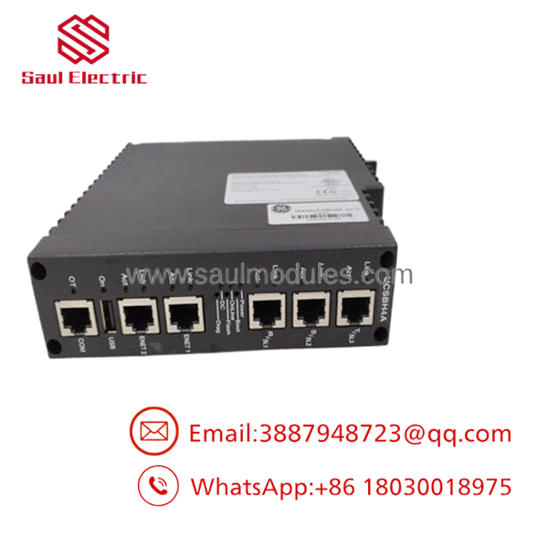
- IS420UCSBH4A
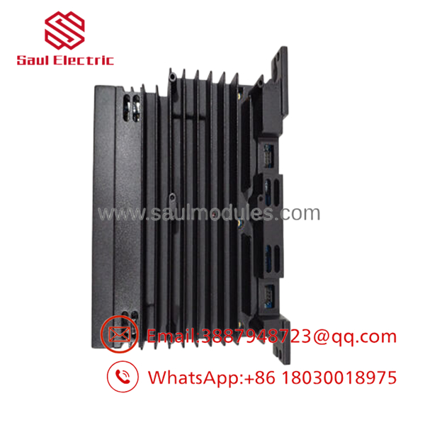
- IS420UCSBH4A
Installation & Field Swap Guide
Stage 1: Pre-Installation Preparation (Estimated Time: 15 minutes)
- ⚠️ Safety First: Coordinate with operators to verify the turbine status before starting maintenance. If the controller is deployed in a Simplex configuration, pulling this module while online will instantly crash the application logic, drop emergency fuel valves, and trigger an immediate, high-stress emergency machinery trip.
- Tools Required: Grounded static-dissipative ESD wrist strap, metric socket drivers, small flathead screwdriver, and an engineering laptop with ToolboxST V6.0 or later.
- Project Backup: Ensure you have a complete, compiled copy of the active project file, network topology mappings, and precise IP addressing schemes saved locally on your laptop before swapping hardware.
Stage 2: Removing the Defective Controller (Estimated Time: 10 minutes)
- Affix your ESD wrist strap to a verified bare-metal panel ground point inside the enclosure cabinet.
- Unplug the 3-pin 28 V DC terminal power harness from the base of the module housing.
- Label and disconnect the four RJ45 Ethernet communication cables from the front faceplate ports, noting their exact positions (IONet R, S, T, and Corporate network).
- Loosen the upper and lower mechanical retention bolts anchoring the controller module box to the cabinet chassis plate frame.
- ⚠️ Note: Pull the module straight forward off its mounting track alignment tabs. Avoid rocking the unit during extraction to prevent stressing nearby structural wire harnesses. Place the pulled card immediately inside an ESD shielding bag.
Stage 3: Seating the New UCSB Controller (Estimated Time: 10 minutes)
- Extract the new IS420UCSBH4A controller from its anti-static factory packaging, handling it strictly by the sheet metal edges.
- Verify that the hardware part codes and structural version suffix (
H4A) match your original hardware design requirements. - Slide the controller module onto the chassis alignment tabs and press firmly until the unit sits completely flush against the mounting plate back wall.
- Tighten the upper and lower retention bolts to secure the module and complete the chassis ground loop.
- Re-insert the four RJ45 Ethernet network plugs into their corresponding ports and plug back in the 3-pin power harness.
Stage 4: Power-On & Software Initialization (Estimated Time: 20 minutes)
- Clear the panel of any loose tools or debris, then turn on the local 28 V DC circuit breaker to power up the unit.
- Monitor the local faceplate boot sequence. The front 8-segment character screen will cycle through self-test codes. When successfully initialized, the status display should display the assigned node status or active run code, and the PWR LED will illuminate solid green.
- Connect your laptop to the controller via the network or through the front RJ-45 serial diagnostic port.
- Launch the ToolboxST programming suite. Establish an online connection, clear the new card’s flash registers, and download your archived application-layer logic, network topology parameters, and specific IP configurations.
- Transition the unit into run mode. If configured in a Dual or TMR architecture, verify that the newly installed controller establishes synchronization with the active sister racks and transitions smoothly into its designated hot-standby or tracking state.
- ⚠️ Troubleshooting Note: If the module throws a permanent “Configuration Blunder” or synchronization fails, open the internal diagnostic fault buffer. Ensure that the active firmware baseline version flashed onto the replacement card matches the firmware running on the remaining system controllers. Redundant architectures require identical firmware baselines to sync and execute data mirroring.
Frequently Asked Questions (FAQ)
What specific purpose do the three separate IONet ports serve on this card?
The three dedicated Ethernet ports (marked as R, S, and T) are utilized to drive GE’s proprietary IONet data fabric. IONet is a high-speed, deterministic Ethernet-based network used exclusively to transfer real-time I/O data between the primary controllers and distributed I/O packs. Having three separate ports allows the UCSB controller to natively support Triple Modular Redundant (TMR) architectures, where three independent data paths run in parallel to provide fault-tolerant control.
Can the flash memory on the IS420UCSBH4A be updated or re-flashed in the field?
Yes. The 2 GB internal solid-state NAND flash memory partition stores the core real-time operating system, active control firmware, and application-layer ladder logic programs. You can update or re-flash this memory in the field using the firmware management utility built into the ToolboxST software application, which allows engineering teams to perform system updates over a standard Ethernet communication link.
Does this controller require an external cooling fan module to operate?
No. The IS420UCSBH4A utilizes an advanced passive convection cooling design. The electronic board components are housed within an integrated metal enclosure that dissipates heat naturally through cooling slots. This fanless design eliminates mechanical wear points and prevents ambient airborne dust, moisture, or chemical residues from being sucked into the electronic component layers.
What is the exact function of the front-panel 8-segment alpha-numeric display?
The built-in 8-segment character display provides local, real-time diagnostic and troubleshooting data directly on the face of the unit. During the startup sequence, it displays specific power-on self-test (POST) status steps. Once the system initializes and goes online, it displays active operational parameters, runtime statuses, or diagnostic fault codes (such as master/slave states, IP errors, or hardware fault flags) without needing a laptop connection.
Since active factory production has transitioned to newer series, what is the status of this stock?
This processor module is available as a verified New Original / New Surplus component sourced from climate-controlled industrial spare parts reserves, distribution overstock, and canceled plant modernization projects. Because factory production lines for these legacy systems have been wound down, sourcing pristine replacements can be difficult. We subject every controller to comprehensive trace checks, power-on self-tests, and network synchronization verification to guarantee out-of-the-box reliability, and back each module with our full 1-year independent warranty.


 Start Chat


