





Description
Product Introduction & Engineering Value
Motor failures rarely occur without warning. Rising winding temperatures, excessive starting time, unbalanced current, and ground faults usually appear long before catastrophic damage occurs. The GE Multilin 369-HI-R-M-0-0 continuously supervises these operating conditions, allowing maintenance personnel to respond before production is interrupted.
Designed for medium-voltage and large low-voltage AC motors, the relay combines protection, control, metering, event recording, and diagnostics in a single package. It integrates easily with industrial automation systems and supports predictive maintenance by providing detailed operating history and fault records.
Technical Specifications
| Parameter | Specification |
|---|---|
| Manufacturer | GE Multilin |
| Model | 369-HI-R-M-0-0 |
| Product Type | Motor Management Relay |
| Protected Equipment | Medium-Sized AC Motors |
| Control Power | HI: 50–300 VDC or 60–265 VAC |
| RTD Option | Built-in 12 RTD Inputs |
| Metering Option | Included (M) |
| Fiber Optic Port | None |
| Standard Communications | Front RS-232, Rear RS-485 |
| Measurement Functions | Current, Voltage, Power, Energy, Frequency, Power Factor |
| Protection Functions | Thermal Overload, Ground Fault, Phase Unbalance, Jam, Stall, Start Inhibit |
| Configuration Software | GE EnerVista™ 369 Setup Software |
Field Application & The “Trench” Experience
A water treatment facility experienced repeated trips on a 1,250 HP raw-water pump during seasonal startup. Conventional overload protection never identified a clear cause, and the maintenance team initially suspected mechanical binding. After replacing the aging protection relay with a 369-HI-R-M-0-0, engineers reviewed the relay’s metering and event logs and discovered excessive current imbalance caused by a deteriorating cable termination.
Once the cable was repaired, the relay recorded balanced phase currents and normal thermal capacity usage. The motor returned to continuous service without additional nuisance trips.
Typical applications include:
- Medium-voltage cooling water pump protection
- Refinery induced-draft and forced-draft fan motors
- Mining conveyor and crusher drive motors
Transparency SOP: QA & Testing
Every New Surplus or professionally refurbished 369-HI-R-M-0-0 is subjected to a documented inspection and functional verification process.
- Confirm the complete ordering code and hardware revision.
- Inspect the LCD, keypad, terminals, and enclosure.
- Verify the high-voltage control power supply operation.
- Simulate CT, RTD, and digital input signals.
- Test relay outputs, alarm logic, and metering accuracy.
- Verify RS-232 and RS-485 communications.
- Complete a burn-in test before anti-static packaging and shipment.
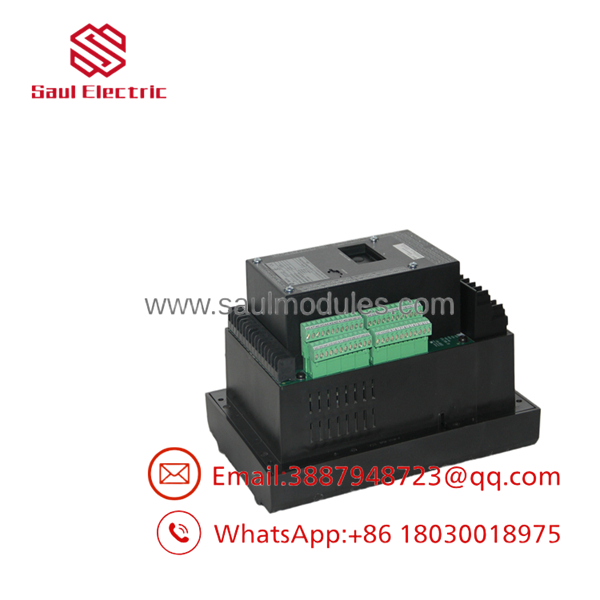
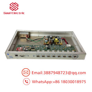
369-HI-R-M-0-0
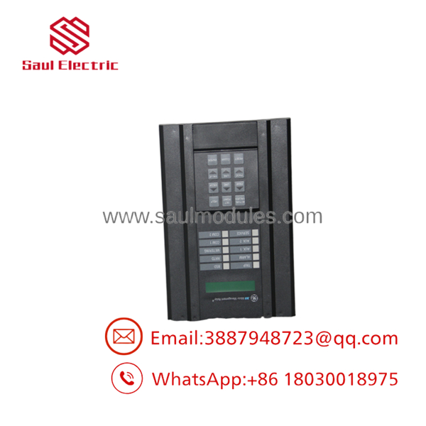
369-HI-R-M-0-0
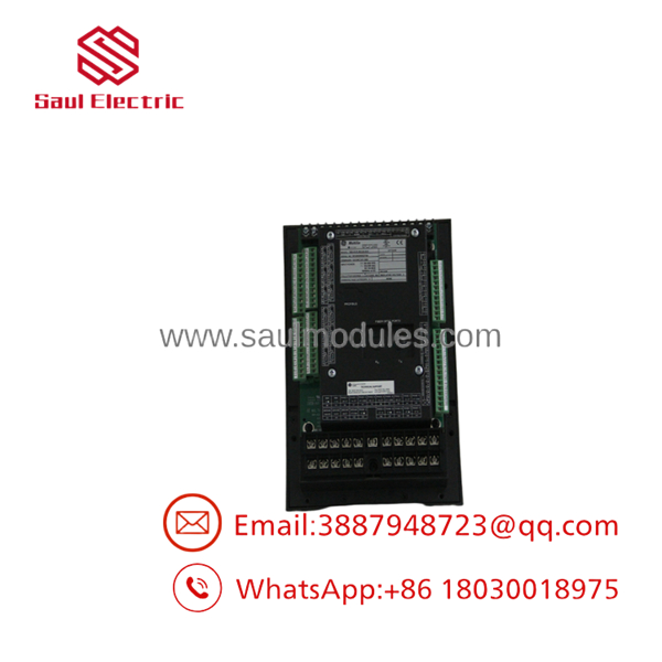
369-HI-R-M-0-0
The Veteran’s Tech Trap Guide
⚠️ Don’t overlook the ordering code. The suffixes define the relay’s hardware capabilities. In this model:
- HI = 50–300 VDC / 60–265 VAC control power
- R = 12 built-in RTD inputs
- M = Metering package
- 0 = No fiber-optic port
- 0 = No optional communication protocol interface
⚠️ Back up the settings first. Before replacing a relay, upload and archive the complete configuration using EnerVista 369. Protection settings, RTD assignments, and motor thermal models are application-specific and should not be recreated manually unless necessary.
PRO TIP: After commissioning, perform a controlled motor start and compare the relay’s thermal capacity usage, current profile, and RTD temperatures with historical records. This establishes a valuable baseline for future predictive maintenance.
Dynamic FAQ
Q1. What does the 369-HI-R-M-0-0 protect?
It is designed to protect and manage medium-sized AC motors, providing thermal overload, phase fault, ground fault, stall, jam, start supervision, and comprehensive motor diagnostics.
Q2. What does the “HI-R-M-0-0” ordering code mean?
- HI – High-range control power (50–300 VDC / 60–265 VAC)
- R – Built-in 12 RTD inputs
- M – Optional metering package
- 0 – No fiber-optic communication
- 0 – No optional communication interface
Q3. Which communication ports are included?
The relay includes a front-panel RS-232 port and rear-panel RS-485 ports as standard. Optional communication protocols are not included in this ordering configuration.
Q4. What software is used to configure the relay?
Configuration, event analysis, firmware management, and diagnostics are performed using GE EnerVista™ 369 Setup Software.
Q5. How is New Surplus inventory verified?
Each relay undergoes hardware verification, display and keypad inspection, control power testing, RTD input simulation, relay output verification, communication testing, and functional inspection before shipment.
Q6. What should be confirmed before installing a replacement relay?
Verify the control power range, CT ratios, RTD wiring, motor protection settings, communication parameters, and saved EnerVista configuration file before energizing the motor. This helps reduce commissioning time and minimizes the risk of unintended trips.



 Start Chat


