





Description
Key Technical Specifications
The model number MMII-PD-1-2-120 breaks down into specific factory hardware options:
| Code Segment | Parameter Option | Configuration Details |
|---|---|---|
| MMII / MM2 | Product Family | Motor Manager II Series |
| PD | Mounting & Interface | Panel Mount with Local LCD Display and control buttons |
| 1 | Option Package 1 | Enhanced Control/Diagnostics: Adds undervoltage auto-restart, pre-trip data logs, history statistics, and 8 programmable switch inputs + 1 analog input (4–20 mA) |
| 2 | Option Package 2 | Enhanced Protection/Inputs: Adds ground fault, locked/stalled rotor, thermistor winding protection, undercurrent/underpower protection, and 2 additional process inputs |
| 120 | Control Voltage | 120 V AC Nominal System Supply Range (80–135 V AC, 50/60 Hz) |
Additional Operational Specifications
- Communication Interface: RS-485 serial port supporting Modbus RTU protocol (1,200 bps to 19,200 bps)
- Physical Hardware Interface: 6 fixed control inputs, 10 programmable switch inputs, 2 contactor control outputs (A/B), and 2 auxiliary programmable relays
- Analog Tracking Range: 4–20 mA input loop for process variable scaling
- Protection Matrix: Advanced thermal model tracking, phase unbalance protection, contactor failure monitoring, hot winding thermistor checks, and overload profiles
- Operating Temperature: 0°C to +60°C
Product Introduction
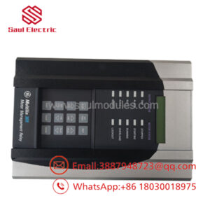
The GE Multilin MMII-PD-1-2-120 is an advanced, panel-mounted intelligent motor management relay belonging to the legacy Motor Manager II (MM2) ecosystem. Engineered primarily for high-density Low Voltage Motor Control Centers (MCCs), this compact, multi-functional asset combines sophisticated protective relaying with programmable starter logic, replacing traditional discrete components like bimetallic overloads, timers, and control relays.
This specific configuration features both optional performance packages, providing facilities with deep motor diagnostics and an extended protection envelope. The unit processes phase currents, ground faults, and winding thermal inputs through an embedded processor to execute internal protective curves. Real-time telemetry, historical faults, and pre-trip profiles can be reviewed directly via the front panel alphanumeric LCD or mapped to centralized SCADA packages via Modbus RTU, preventing catastrophic motor asset burnouts and reducing unscheduled plant downtime.
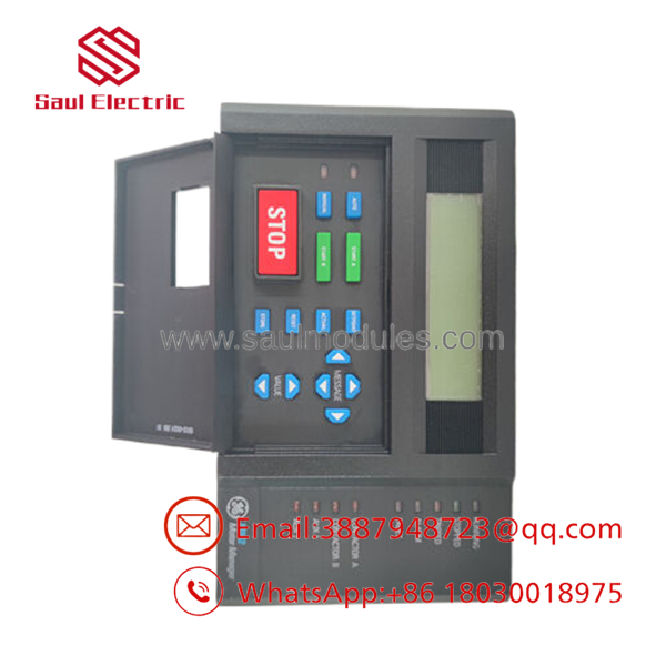
- MMII-PD-1-2-120
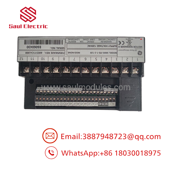
- MMII-PD-1-2-120
Installation & Configuration Guide
Stage 1: Pre-Installation Preparation
- ⚠️ Safety First: Low-voltage motor control centers contain hazardous line voltages and high short-circuit energy potential. Ensure the targeted feeder breaker is racked out, completely isolated, and locked out/tagged out (LOTO). Use a verified digital multimeter to check all phase terminals and control supply lines to confirm zero voltage before handling wiring blocks.
- Tools Required: 3.5mm flathead screwdriver, Phillips screwdriver, wire label markers, wire strippers, and a laptop with EnerVista MMII software configuration tools.
- Data Backup: If replacing a running unit, connect via Modbus or use the front display to manually document the active thermal overload configurations, current transformer (CT) ratios, full load amps (FLA), starter type selection, and Modbus device addresses.
Stage 2: Removing the Old Module
- Attach your grounded anti-static (ESD) wrist strap to the bare metal structural frame of the MCC bucket block.
- Carefully label each terminal wire bundle attached to the rear pluggable block headers.
- Unplug the terminal headers from the back panel of the unit; use care when disengaging these high-density connections to avoid twisting the terminal chassis.
- Back out the integrated panel-mounting brackets located on the sides of the relay case, then slide the unit forward out of the sheet metal panel cutout.
- ⚠️ Note: Put the removed hardware directly into an ESD shielding pouch to protect the internal control circuitry during transport.
Stage 3: Installing the New Module
- Check that the cutout dimensions on the panel door match the MMII panel-mount footprint (approximately 7.10″ W × 7.36″ H).
Power Duke
- Slide the replacement MMII-PD-1-2-120 housing through the front door opening. Secure it from behind using the panel mounting clamps, torquing them until the front gasket compresses flush against the door panel to maintain its IP53/NEMA 12 environmental seal.
- Re-engage the pluggable terminal wiring blocks into their corresponding slots on the back panel. Ensure the headers snap securely into place to prevent loose connections under typical machinery vibration.
- Self-Checklist:
- [ ] Panel mount gasket is compressed evenly with no gaps.
- [ ] Control power lines are routed explicitly to the 120 V AC designated terminals.
- [ ] External CT sensor connections match the designated Phase A/B/C terminal inputs.
Stage 4: Power-On & Testing
- Restore the 120 V AC control voltage to the module, keeping the main 3-phase motor power disconnected or isolated via the isolation switch.
- Watch the front panel display: the local LCD interface should light up, and the unit will execute a power-on self-test (POST). The status indicator should stabilize into normal run parameters without throwing a flashing hardware error.
- Establish communication using the EnerVista MMII software package. Upload the pre-documented settings profile, making sure the CT ratios and motor FLA constants match the nameplate of the connected equipment.
- Execute a dry control check: command local “Start” and “Stop” functions via the front panel buttons or software to verify that the contactor control relays actuate correctly before putting the motor under load.
- ⚠️ Troubleshooting Note: If the unit logs an immediate
Phase UnbalanceorUndercurrenttrip code upon primary line start, verify the external CT orientation and check that the secondary current loops are wired with the proper phase rotation.
Frequently Asked Questions (FAQ)
Can I drop this panel-mount “PD” module into a standard chassis-mount slot?
No, the “PD” designation indicates that this specific device is built with a panel-mount housing that features a front-panel alphanumeric LCD screen and an integrated navigation keyboard interface. Chassis-mount variants (designated “CD”) are optimized for blind interior sub-panel mounting and lack the display layout. The physical dimensions and mounting footprint between these two variants are different.
What parameters are enabled by “Option Package 1 and 2” on this relay?
This unit features a fully expanded feature set. Option 1 adds process control functions, 10 total process inputs, undervoltage auto-restart, and advanced diagnostics (pre-trip records and history logs). Option 2 expands the safety profile by integrating dedicated ground fault tracking, locked/stalled rotor detection, undercurrent/underpower limits, and a dedicated internal thermistor circuit to monitor high motor winding temperatures.
How does the undervoltage auto-restart feature work after a power sag?
When a momentary voltage dip or total loss of auxiliary power drops the control rail below the threshold, the MMII logs the event. Once steady 120 V AC control power returns within a user-defined time window, the internal logic safely re-energizes the contactor lines using pre-programmed staggered restart timing constants. This prevents multiple heavy pumps or fans from drawing an excessive current spike on the substation bus simultaneously.
Do I need to manually configure the Modbus baud rate on a new surplus module?
Yes. Brand new or factory surplus units initialize with default factory communication settings (usually 9600 bps, Address 1, No Parity). If the unit is connecting to an established RS-485 multi-drop network loop inside a motor control center, you must use the front interface panel or a localized serial connection to adjust the communication properties to match your SCADA master workstation specifications.
Why use a legacy New Surplus component instead of upgrading the entire MCC bucket?
Upgrading a modern motor protection relay framework often requires changing the physical footprint, modifying sheet metal enclosures, rewiring terminal blocks, and refactoring downstream SCADA automation code. Utilizing a genuine OEM New Surplus MMII-PD-1-2-120 unit allows your engineering team to drop the replacement directly into the existing panel slot during a standard maintenance window. This eliminates the engineering costs and downtime associated with a full system modernization.

 Start Chat


