





Description
Key Technical Specifications
| Parameter | Specification / Value |
| Number of CT Inputs | 4 channels total (3 × Phase CT, 1 × Ground CT) |
| Current Rating (CT) | 1 A / 5 A nominal secondary (software/jumper selected) |
| CT Thermal Withstand | 3 × nominal current continuously; 100 × nominal for 1 second |
| Number of VT Inputs | 4 channels total (typically Phase A, B, C, and Neutral/Open-Delta) |
| Voltage Rating (VT) | 0 to 300 V AC nominal scale tracking range |
| VT Input Isolation | 2 kV AC isolation for 1 minute across inputs and chassis ground |
| Frequency Tracking | Native 50 Hz and 60 Hz electrical networks |
| Terminal Mounting | Horizontal block alignment, pluggable screw terminals |
| Acceptable Wire Gauge | 12 AWG standard application; 10 AWG maximum solid copper wire |
| Applicable Standards | IEC 60255 compliance, ANSI C37.90 surge protection profile |
| Operating Temperature | −40°C to +55°C (−40°F to +131°F) |
| Module Dimensions | Approximately 15 cm L × 18 cm W × 4 cm H (5.9 × 7.1 × 1.6 inches) |
| Net Weight | 1.2 kg (2.6 lbs) |
Product Introduction
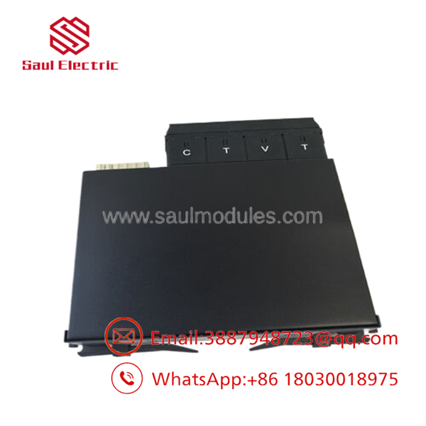
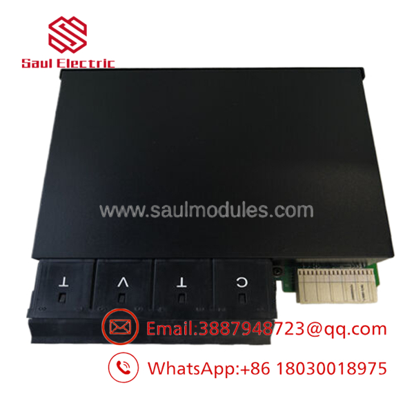
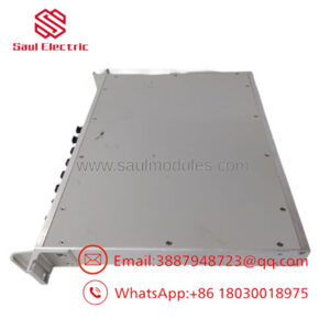
The GE Multilin UR8FH is a foundational CT/VT measurement input card engineered for the modular Universal Relay (UR) platform. This card plays a critical protective role by physical scaling of secondary transformer lines, capturing raw analog waveform currents and voltages from utility grids and heavy plant infrastructure. The relay’s main CPU uses this isolated stream to drive protective algorithms including distance calculation, differential indexing, and directional overcurrent handling.
Equipped with three-phase current inputs, a high-accuracy ground current path, and four direct voltage transformer terminal taps, the UR8FH supports high-precision analog data sampling. Its internal circuitry maintains galvanic separation to shield delicate backplane logic boards from high-energy substation surges. Its horizontal slot integration matches standard chassis variants across the full UR lineup, making it a drop-in replacement part during scheduled generation or transmission rack overhauls.
【Core Strategy 1: SOP Quality Transparency】
Every modular card entering out-of-factory surplus pipelines is put through a clear electrical and load diagnostic regime. We recognize that sub-component drifting within protective relay matrices puts major capital hardware at risk.
1. Inbound Inspection & Traceability
- Origin Audits: Serial markings are checked against original batch records from the Markham, Ontario manufacturing source.
- Component-Level Inspection: Modules are assessed under static-controlled magnification to identify signs of track degradation, micro-fractures near screw connection rails, or thermal stress on filtering capacitors.
- Mating Connection Review: Rear multipin connector headers are verified to ensure pins are parallel and free of structural metal bending.
2. Live Functional Testing
- Test Rack System: The UR8FH module under test is keyed into a live, operational GE Universal Relay test chassis tied to an OMICRON secondary injection test set.
- Current and Voltage Injection: We sweep current inputs from 0.5 A up to 15 A and voltage lines up to 280 V AC to track precision linearity against factory specs. Live telemetry graphs are verified via the relay’s front LCD and the EnerVista software console.
- Thermal Stress Burn-In: Cards undergo a continuous 12-hour energized dwell test at 50°C to reveal latent component breakdown before the module is approved for field service.
3. Electrical Parameter Testing
- Hipot Verification: Dielectric voltage withstand procedures are conducted at 2 kV AC for 60 seconds relative to the frame ground bar.
- Insulation Resistance: Using a dedicated insulation tester, internal isolation barriers are checked to ensure they measure greater than 20 MΩ at 500 V DC.
4. Firmware & Configuration Verification
- Boot-Level Synchronization: Module diagnostic codes are matched to current relay system microcode levels. Hardware version IDs are read out directly using the EnerVista interface to verify accurate firmware identification.
- Connector Integrity: Pluggable terminal blocks are mechanically validated to hold target wire torques.
5. Final QC & Packaging
- Static Protective Bags: Validated units are immediately placed inside sealed static-shielding bags.
- Shock Protection: Modules are enclosed within impact-absorbing foam frames inside thick corrugated outer boxes. The container is labeled with standard identification numbers, batch codes, and a signed QC completion tag.
- UR8FH
- UR8FH
Installation & Configuration Guide
Stage 1: Pre-Installation Preparation
- Estimated Time: 20 minutes
- ⚠️ Safety First: Confirm the target breaker is open and isolated. Short-circuit all secondary CT circuits externally using dedicated shorting terminal blocks before opening any relay wiring paths. Never open-circuit a live CT secondary path, as this produces hazardous high voltages. Disconnect auxiliary station control power and wait 5 minutes before pulling parts.
- Tools Required: ESD wrist strap, flat-head and #2 Phillips screwdrivers, a wire label printer, and a digital multimeter.
- Data Backup: Save the target relay’s settings file (
.ursparameter extension) via an active EnerVista connection. Document the specific physical slot mapping (Slots B through G) where the target module is seated.
Stage 2: Removing the Old Module
- Estimated Time: 10 minutes
- Steps:
- Secure your ESD wrist strap to a dedicated structural panel ground pin.
- Unplug the terminal block blocks by backing out the captive locking hardware screws on each side of the wiring harness.
- Loosen the upper and lower structural retaining screws built into the metal flange of the UR8FH card face.
- Pull the card firmly out toward you using the handle clips, ensuring it slides evenly along the interior nylon slot tracks.
- Check that the interior guide channels are clear of debris or dust buildup before attempting replacement insertion.
Stage 3: Installing the New Module
- Estimated Time: 15 minutes
- Steps:
- Verify the replacement module part number explicitly matches the original designation.
- Slide the module into the targeted slot tracks, maintaining linear alignment until the rear connector seats cleanly into the primary backplane socket.
- Hand-tighten the upper and lower faceplate fastening screws to lock the card flange flat against the chassis edge.
- Check the shorting terminal setup, then carefully plug the external current and voltage transformer wiring block into the front connector array.
- Self-Checklist:
- [ ] Flange mounting screws secured flat without gap tolerances.
- [ ] Direct alignment of all field wiring block headers.
- [ ] Removal of temporary external shorting screws after verifying the card is fully seated.
Stage 4: Power-On & Testing
- Estimated Time: 15 minutes
- Power-On Steps:
- Restore control voltage power to the primary relay power supply card.
- Check the front display panel. Ensure the Relay In Service LED illuminates and that no “Hardware Mismatch Slot X” error flags display on screen.
- Open the EnerVista connection utility, navigate to the hardware configuration module menu, and verify the slot registers the new module accurately.
- Perform low-level current injection tests to verify phase rotation indicators and matching vector angles on your measurement display screens.
- ⚠️ Troubleshooting Note: If a self-test failure indicates a slot calculation breakdown, remove the card to check if any rear header pins have bent or if the module configuration settings file requires a firmware calibration step.
【Core Strategy 2: Technical Pitfall & Survival Guide】
1. 1 A vs. 5 A CT Jumper Selection Traps
The accepts both 1 A and 5 A secondary CT inputs, but matching configuration registers must be correctly selected within your EnerVista parameter files. ❗ Mismatching these parameters will distort protection settings. Setting the software profile to 1 A while feeding a 5 A secondary signal will rapidly saturate the internal input transformers during a fault, preventing the relay from executing a trip command. Always cross-check the nameplate ratings of your physical current transformers against your active software profile before testing.
2. Live Current Transformer Isolation Failures
The most common hazard when replacing a CT/VT card is failing to ensure that external CT secondary circuits are securely shorted before removing the pluggable wire terminal blocks. The pluggable terminals have built-in mechanical shorting actions, but field dirt or physical distortion can cause these mechanisms to fail. Treat every wire harness as an open-circuit hazard: utilize external shorting links on your terminal strip before unplugging the module interface blocks.
3. Backplane Alignment and Pins Bend
The UR module design relies on a matrix of backplane header pins to route signals between cards. If a module is inserted at an angle or forced into a slot with worn guide rails, these pins can bend or break. ❗ Never use excessive force to seat a module. If the card flange does not slide completely flush with the external framework under gentle pressure, pull the module back out and inspect the pins using a flashlight. Repairing a damaged backplane requires completely dismantling the relay chassis.
4. Wire Gauge and Terminal Constraints
The horizontal terminal block blocks accept wire gauges up to 10 AWG, but using overly stiff, solid-core 10 AWG wire can stress the solder joints on the card’s internal circuit board if the wire bundle is bent sharply inside the panel door. Use high-strand-count, flexible 12 AWG control wire for CT connections whenever possible. This balances required current capacity with adequate strain relief, preventing the screw blocks from cracking under mechanical stress.
5. Multi-Slot Board Mapping Bugs
When swapping a CT/VT module during a hardware upgrade or moving components between different Universal Relay units, you must ensure the card is placed into the exact slot letter defined in the original application logic. If you insert a replacement card into Slot F instead of Slot W, the internal FlexLogic equations will monitor dead inputs while looking at the wrong slot. This leaves your primary feeder unprotected even though the relay shows a normal status indication. Always match your hardware layout to your logic mapping sheets.
Frequently Asked Questions (FAQ)
Can I hot-swap the module while the main Universal Relay is powered up?
Yes, the mechanical architecture of the GE Universal Relay platform allows for hot-swapping individual I/O and CT/VT cards without turning off the primary power supply. However, you must first ensure that all secondary CT circuits are externally shorted and that all VT lines are isolated before pulling the card. While the chassis can remain energized, powering down the control voltage during module replacement is still recommended whenever possible to minimize risk.
What is the practical operational difference between the card and the UR8LH card?
The primary difference lies in the specific voltage transformer inputs and frequency handling characteristics. The is designed as a standard 4 CT / 4 VT input card optimized for typical 50/60 Hz utility and industrial distribution systems. Other variants, such as the 8LH or 8NH, feature alternative channel configurations (e.g., highly sensitive ground CT paths or specific voltage measurement scales for generator protection). You cannot swap an 8FH card for an 8LH card without modifying the physical wiring layout and internal logic configuration.
What should I do if the relay displays a “Module Incompatible” error after installation?
This error code indicates that the firmware version running on the main CPU card does not support the internal revision index of the replacement module. To resolve this, you will need to connect via EnerVista software and either update the main relay firmware to a version that supports the new module or downgrade the card profile properties inside your settings configuration workspace.
Can I mix 1 A and 5 A secondary current transformers on the same module?
The module’s physical hardware channels are capable of monitoring either 1 A or 5 A ranges, but the specific input scaling factors must be configured for each channel within the software setpoints. For example, channels 1 through 3 can be set to 5 A for phase protection while channel 4 is configured for a 1 A ground input. You must ensure that the secondary ratings of the physical CTs match the specific settings applied to each channel register.
Why is it important that this module uses a horizontal configuration layout?
The Universal Relay chassis comes in both horizontal and vertical enclosure configurations, which determines how the internal cards orient into the rear backplane slot tracks. A horizontal module variant like the matches the slot orientation and label layouts of horizontally oriented UR chassis frames. Attempting to fit a horizontal card into a vertically oriented relay enclosure will cause mounting alignment issues and make it difficult to trace wire labels accurately.

 Start Chat


