





Description
Key Technical Specifications
| Parameter | Specification Value |
| Control Power Supply | Standard High: 90–300 VDC or 70–265 VAC (at 50/60 Hz) |
| Voltage Input Capability | 57–400 VAC (Line-to-Neutral) / 100–690 VAC (Line-to-Line) |
| Current Inputs (CT Suffix) | Dual rated for 1 A or 5 A nominal secondary circuits |
| Metering Metrology Type | True RMS tracking sampling at up to 256 samples per cycle |
| Programmable Output Relays | 4 Total (Form C contacts rated at 5 A resistive, 250 VAC) |
| Programmable Switch Inputs | 4 Dry contact inputs (for breaker status or dual-setting selection) |
| Analog Transducer Outputs | 4 Isolated channels, software selectable for 0–20 mA or 4–20 mA |
| Process Analog Inputs | 1 Channel, 4–20 mA input loop |
| Serial Communication Interfaces | 1x Front RS232 panel port, 2x Rear isolated RS485 connections |
| Communication Protocols | Modbus RTU (up to 19.2 kbps), DNP 3.0 Level 2 |
| Harmonic Measurement | Total Harmonic Distortion (THD) reporting |
| Enclosure Construction | Flame-retardant industrial grade ABS/Polycarbonate |
| Front Protection Rating | IP54 / NEMA 2 dust-tight when door clamp is fully engaged |
| Dimensions & Weight | 144 x 144 x 140 mm frame size; Approx. 3.75 lbs (1.70 kg) |
Product Introduction
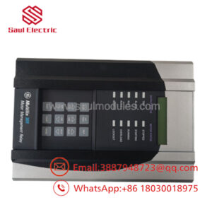
The GE Multilin PQMII-T20-C is a robust panel-mounted, 3-phase power quality monitor that bridges the gap between digital telemetry and localized system control. Built for installation in heavy industrial electrical infrastructure, motor control centers (MCCs), and utility substations, it reads true RMS currents, voltages, power factors, and frequency deviations. It safeguards upstream hardware by providing automated alarm and control actions based on real-time distribution line parameters.
The specific “T20-C” syntax marks this device as a high-tier option package within the PQM II lineup. The “T20” suffix integrates 4 isolated 4–20 mA or 0–20 mA analog outputs and an extra rear RS485 communication node to feed telemetry to a remote DCS or PLC. Simultaneously, the “C” option adds comprehensive local control capabilities: 4 programmable digital switch inputs to read external breaker positions and 4 independent Form C output relays. This eliminates the need for individual external transducers, auxiliary status relays, and dedicated PLC input blocks.
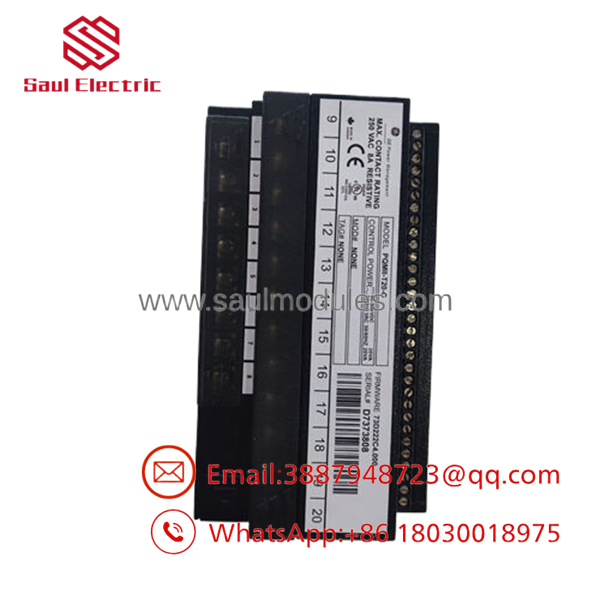
- PQMII-T20-C
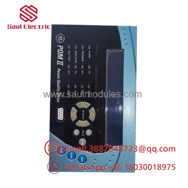
- PQMII-T20-C
Installation & Configuration Guide
Stage 1: Pre-Installation Preparation (Estimated Time: 10 minutes)
- ⚠️ Safety First: Notify operations of coming panel bus monitoring downtime. Ensure that all main voltage sensing circuits are securely disconnected or isolated at the switch block. Never open-circuit a live Current Transformer (CT) secondary. Confirm all CT shorting block links are inserted and tightly screwed down before removing any current wires on the meter block.
- Tools Required: ESD wrist strap, PH1 and PH2 screwdrivers, insulated wire markers, Fluke 115 multimeter, and a tablet or smartphone for wiring verification.
- Data Backup: Link your laptop to the faceplate RS232 port with EnerVista PQM Setup software. Pull and archive the running configuration profile (
.pqmsetup file) to preserve programmed node maps, custom relays, and transformer scaling values.
Stage 2: Removing the Old Module (Estimated Time: 5 minutes)
- Verify the CT shorting block pins are physically inserted.
- Unscrew the protective rear terminal block shielding layout. Label every single incoming landing wire according to its designation.
- Back out the terminal screws on the rear blocks and detach the ring/spade lugs. Never pull hard against old wiring harnesses.
- Loosen the four heavy clamping frames positioned on the sides of the meter housing.
- Push the old PQM II body straight out through the front switchgear door panel cutout. Clean any old rubber compression dust off the metal frame boundary.
Stage 3: Installing the New Module (Estimated Time: 10 minutes)
- Put on a grounded ESD wrist strap before breaking the protective bag seal on the new PQMII-T20-C.
- Press the new unit squarely into the panel cutout, ensuring the integrated compression frame seal rests flush with the exterior door facade to maintain the dust-tight IP54 rating.
- Tighten the four mounting screw clamps iteratively until the housing frame is securely fixed against the sheet metal door cutout. Do not use an impact driver; over-torquing will fracture the composite housing tabs.
- Configuration Clone: Power up the control circuit lines (Terminals A1/A2) independently. Load your archived
.pqmparameters file using EnerVista setup software. Pay absolute attention to confirming that the CT secondary selections match the plant infrastructure wiring specifications. - Re-terminate the wire ring lugs back onto the terminal block points. Unscrew and remove the CT shorting blocks only after confirming that the loop across terminals H1 through G12 is complete.
❗ Configuration Check:
[ ] Target CT secondary scale config mirrors the active line profile.
[ ] Wiring terminals match factory distribution diagram specifications.
[ ] Front sealing ring sits completely flush without gaps.
Stage 4: Power-On & Testing (Estimated Time: 5 minutes)
- Re-energize the upstream voltage sensing circuit paths.
- Verify the startup sequence on the backlit LCD. The home parameters screen should resolve with the system status indicating a solid green operational state.
- Run a localized hardware diagnostic routine via the faceplate buttons to crosscheck that phase voltages match physical bus values on the test rails.
- Verify network communication by checking that the TX/RX indicators on the rear RS485 loop are blinking actively when queried by the master PLC/SCADA controller.
Strategic Quality Control & Inspection Process
Because the GE PQMII series is no longer actively produced by the OEM, maintaining structural availability requires a highly methodical and transparent quality control validation pipeline at our depot.
- Inbound Inspection & Traceability: Incoming components undergo verification matching. Serial markers are cross-referenced to eliminate counterfeit parts. Every chassis undergoes physical analysis for board corrosion, aging capacitors, cracked display windows, or structural damage to terminal blocks.
- Live Functional Testing: Units are benched on an official test chassis replicating dynamic substation loads. We execute complete power-on self-test cycles, check voltage and current input balances across all phases, and evaluate step metrics for the 4 isolated analog outputs using precision measuring equipment. The 4 integrated control relays are cycled multiple times under resistive load profiles to confirm contacts operate without stickiness or arcing degradation.
- Electrical Parameter Testing: A 500 V Megger insulation test is run between the active primary power rails and the frame ground points. We verify that isolation resistance values remain strictly above 10 MΩ to prevent component breakdown under field conditions.
- Firmware & Configuration Documenting: The exact internal firmware revision code is logged in our tracker system. System flags and registers are normalized back to factory defaults so the device arrives clean and ready for a fresh drop-in site upload.
- Final QC & Packaging: Following inspection sign-off, the unit is wrapped in thick ESD shielding, encased within heavy-wall bubble shock packaging, and loaded into an uncompromised corrugated shipping carton complete with its technical verification pass card.
Frequently Asked Questions
Can this PQMII-T20-C model be hot-swapped while the distribution line is live?
No, it cannot. While the physical meter configuration is panel-mounted on the switchgear door, pulling or disconnecting the wiring terminals under load will open-circuit active Current Transformer paths. This will create high-voltage electrical arcing, which will destroy the terminal block interface and present an active arc-flash risk to the technician. Isolate your sensing loops and secure shorting links before swapping units.
What is the mechanical difference between a PQMII-T20-C and a -A?
The letter “A” at the end of the extended product designation stands for the Power Analysis software option package. This enables advanced internal computing features such as waveform capture tracking, a triggered trace memory log, and comprehensive harmonic analysis up to the 63rd order. Most models in circulation include this feature set enabled via internal firmware configurations.
My original device does not have the “-C” designation. Can I swap this unit in?
Yes, you can use a as a direct replacement for a base PQMII-T20 unit. The physical dimensions, voltage inputs, current transformer connections, and analog outputs match perfectly. The only difference is that the “-C” model provides 3 extra programmable control relays and 4 switch input channels on the terminal block which can simply be left unpopulated if your system prints do not utilize them.
What happens if the replacement meter has a different internal firmware code?
Standard Modbus register addresses for polling voltage, current, and power factor stay uniform across firmware generations. However, if your SCADA host relies on specialized register configurations unique to very old firmware releases, mismatch errors can occasionally cause communications drops. Let us know what firmware revision your old unit runs, and we can match or flash the appropriate level prior to dispatch.
Why are your prices lower than standard industrial retail direct lines?
We procure original equipment components directly through industrial overstock channels, project modifications, and liquidated capital assets. By acquiring genuine surplus items in volume, we sidestep typical industrial distribution markup layers and pass those cost benefits on to engineers and procurement teams, while backing every single item with our independent 1-year replacement warranty.


 Start Chat


