





Description
Key Technical Specifications
| Parameter | Value / Specification |
| System Framework | GE Speedtronic Mark V Turbine Control Series |
| Functional Nomenclature | PRG-MODEM (Programming Modem Unit) |
| Communication Interface | 1 x RS-232 point-to-point asynchronous serial port |
| Peak Serial Baud Rate | Up to 115,200 bps continuous data flow |
| Input Power Demand | +5 VDC nominal operating input |
| Mounting Envelope | Specialized interface frame footprint |
| Data Synchronization | Formatted for legacy asynchronous remote diagnostic polling |
| Diagnostic Feedback | Onboard transmit/receive physical tracking loops |
| Circuit Board Shielding | Industrial-grade component conformal coating layer |
| Operating Temperature | −40 to +85°C (−40 to +185°F) heavy industrial window |
Product Introduction
The GE PRG-MODEM is a dedicated, legacy programming and communication interface module engineered specifically for the Speedtronic Mark V gas and steam turbine control series. This compact interface card functions as a bridge that enables remote configuration, program downloading, and long-distance engineering workstation connections to the core processing racks. It translates high-level engineering software parameters into serial telemetry frames required for dial-up diagnostic loops or localized isolated logic checks.
Featuring a robust RS-232 interface, the PRG-MODEM handles data transfer speeds up to 115,200 bps across a wide operating temperature envelope of −40 to +85°C. Its hardware layout is designed to filter out the severe electromagnetic interference (EMI) commonly found inside utility-scale generator enclosures. This helps prevent data packet corruption and dropped connections during remote monitoring sequences or emergency online troubleshooting.
Installation & Configuration Guide
Stage 1: Pre-Installation Preparation (Estimated Time: 15 minutes)
- ⚠️ Safety First: The PRG-MODEM provides direct diagnostic access to the active turbine control processor layer. Never modify this board’s interfaces while the turbine application loop is executing live parameters without a backup connection. Isolate the system configuration link and lock out/tag out (LOTO) the low-voltage DC auxiliary power paths feeding the communication card slot.
- Tools Required: Grounded static-elimination wrist strap, small jeweler’s slot screwdriver, digital multimeter (DMM), fine-point wire marking tags.
- Data Backup: Before swapping components, run your local HMI or command terminal tool to back up the target communication register parameters, baud rates, and parity settings configured inside the Mark V operating tree.
Stage 2: Removing the Old Module (Estimated Time: 5 minutes)
- Affix your anti-static wrist strap to a bare metal chassis structural beam inside the Mark V cabinet enclosure.
- Label and carefully unthread the thumbscrews on the active RS-232 serial cable connected to the card face. Unplug the line straight to avoid bending the pins.
- Loosen the physical retaining screws holding the small PRG-MODEM board module to its plastic standoffs or mounting framework.
- Lift the board straight outward from its alignment pins, ensuring it clears neighboring backplane logic channels. Place the card into an ESD shield wrap.
Stage 3: Installing the New Module (Estimated Time: 10 minutes)
- Extract the new PRG-MODEM board from its factory anti-static packaging.
- Configuration Clone: Compare the layout of the old board and the replacement card side by side. Carefully examine and duplicate any tiny hardware trace jumpers or DIP switch settings that configure things like line termination resistors, echo controls, or RS-232 hardware handshaking modes.
- Seat the card squarely onto its mounting standoffs or localized chassis footprint, and tighten the small securing screws down evenly.
- Align and plug the labeled RS-232 communication connector back into its port, turning down the retention thumbscrews snugly to protect against vibration loosening.
Stage 4: Power-On & Testing (Estimated Time: 15 minutes)
- Restore the +5 VDC auxiliary control power lines to the interface segment.
- Monitor the local system communication diagnostic indicators during boot:
- Power and baseline interface lights should stabilize into normal standby behavior.
- ⚠️ Troubleshooting: If the connected console or engineering interface tool reports an “Unable to Connect” loop fault, disconnect power and check that your baud rate configuration jumpers aren’t mismatched.
- Open your engineering communication workspace to execute a simple loopback test or point-to-point query. Confirm that data transmission blocks flow cleanly across the new PRG-MODEM before clearing the cabinet for standard automated production.
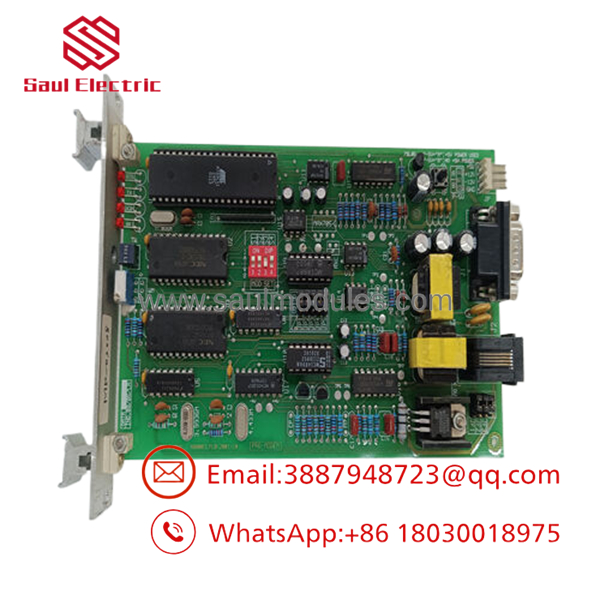
- PRG-MODEM
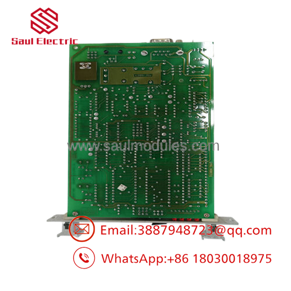
- PRG-MODEM
Frequently Asked Questions (FAQ)
Can I hot-swap the PRG-MODEM card while the Mark V panel is live?
No, the PRG-MODEM should not be hot-swapped while communication is active. Pulling the module while data is moving can cause voltage transients on the serial logic traces, which can lock up the adjacent panel communication processor card. Always turn off the local control circuit power before removing the board to prevent data corruption or component damage.
What do the numbers “03 50 54B” on the card label indicate?
The string 03 50 54B represents the specific engineering revision level, manufacturing batch code, and component configuration layer applied by General Electric during that production run. To ensure backward compatibility and smooth system integration with your current Mark V software and cable setup, try to match these revision suffix strings whenever you replace a board.
Can I run this modem module at baud rates higher than 115,200 bps?
No, the onboard logic chips and transceiver circuits on the PRG-MODEM are optimized for legacy asynchronous serial communication, with a maximum data throughput of 115,200 bps. Attempting to force higher speeds through your programming software will result in timing mismatches, framing errors, and dropped data packets across the connection link.
Does this board require its own independent firmware flashing during a swap?
No, the PRG-MODEM operates as a hardware-level signal converter and interface bridge. It does not run an independent operating system or require local firmware compilation. Once you mirror the physical board jumper blocks to match your original card’s layout, it will communicate out of the box using your existing Mark V application parameters.
Why do you sell these modules as “New Surplus” rather than brand new factory stock?
Since General Electric transitioned support for the legacy Speedtronic Mark V platform to newer control systems, these modules are no longer in active production. Our stock consists of New Original / New Surplus units, which are unused factory spares acquired from plant liquidations, project surpluses, or storage reserves. This allows you to find authentic replacement parts without long factory lead times.



 Start Chat


