





Description
Key Technical Specifications
| Parameter | Value |
|---|---|
| Manufacturer | GE (General Electric) |
| Model Number | PWB68A993125 |
| Product Type | Printed Circuit Board (PCB) |
| Board Function | Screen Gate / Filter Board |
| Installation | OEM equipment replacement board |
| Construction | Factory-assembled electronic PCB |
| Cooling | Passive air cooling |
| Service Environment | Industrial electronic equipment |
| Maintenance | Replace as complete assembly; component-level repair is not recommended |
| Lifecycle Status | Mature / Obsolete |
| Recommended Stocking | Maintain 1–2 units for critical equipment |
| Condition | New Original / New Surplus |
Product Introduction & Supply Chain Strategy
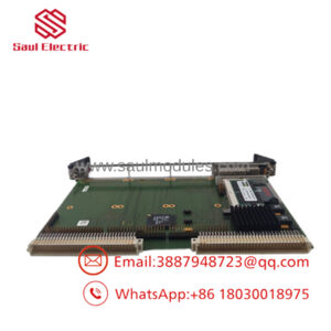
The GE PWB68A993125 is an OEM printed circuit board identified as a Screen Gate / Filter Board used within selected GE industrial electronic systems. It provides signal conditioning and filtering functions required for reliable equipment operation and should always be replaced with the correct OEM part number.
Because this board is no longer widely available through normal OEM channels, maintaining New Surplus inventory is the most effective strategy for reducing Total Cost of Ownership (TCO). Plants relying on this hardware should establish buffer stock, monitor lead time variability, consolidate qualified suppliers, and consider a last-time-buy before market availability declines further.
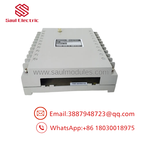
- PWB68A993125
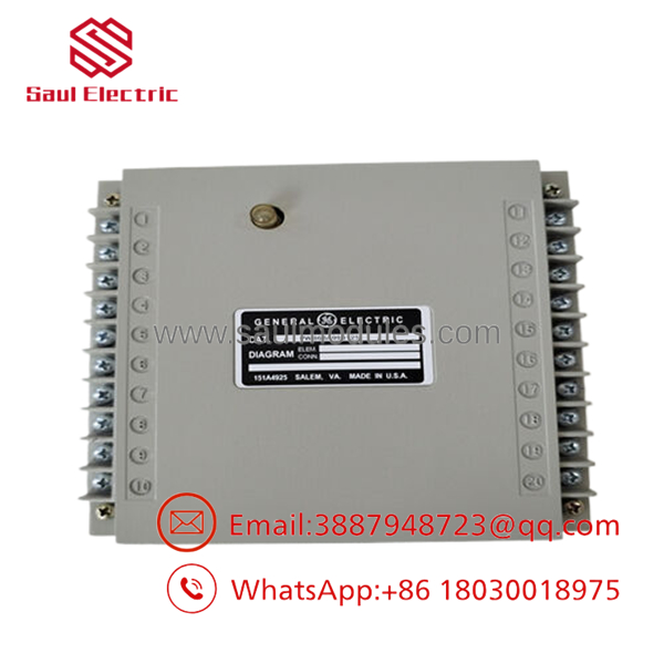
- PWB68A993125
Installation & Configuration Guide
Stage 1 – Pre-Installation (Preparation & Safety)
- Perform Lock-Out/Tag-Out (LOTO).
- Disconnect all input power.
- Wear a grounded ESD wrist strap.
- Photograph all cable locations and connector orientations.
- Record any jumper or hardware configuration before removal.
Stage 2 – Removal
- Disconnect ribbon cables and harnesses carefully.
- Remove mounting hardware.
- Extract the PCB vertically without stressing connectors.
- Inspect the backplane and connectors for contamination or bent contacts.
Stage 3 – Installation
- Confirm the replacement part number is PWB68A993125.
- Install the board using identical hardware.
- Reconnect every cable according to the recorded wiring.
- Verify all connectors are fully seated.
Stage 4 – Power-On & Testing
- Restore system power.
- Confirm all status indicators operate normally.
- Execute OEM diagnostics.
- Verify communication and equipment functionality before returning the system to production.
Firmware / Software Versions & Upgrade Notes
- This PCB itself normally does not contain user-programmable application software.
- If installed in equipment containing processor modules, verify firmware compatibility with the complete system.
- Record firmware revisions before replacing associated controller boards.
- Avoid simultaneous firmware and hardware changes during the same maintenance window.
- Perform complete functional verification after replacement to confirm proper communication and operation.
Frequently Asked Questions (FAQ)
Q1. Is this a New Original product?
Yes. The recommended inventory option is New Original / New Surplus. It is not used, repaired, or refurbished.
Q2. Why is New Surplus more expensive than refurbished boards?
New Surplus inventory has never been placed into production service. It offers significantly lower reliability risk, longer expected service life, and reduced downtime compared with refurbished electronics.
Q3. Is PWB68A993125 still manufactured?
Available market information indicates that this board is primarily supplied from remaining inventory rather than current production, making advance procurement advisable for critical facilities.
Q4. Can this PCB be hot-swapped?
No. Always isolate equipment power before removing or installing the board to prevent damage to the PCB and surrounding electronics.
Q5. Does replacing this board require configuration?
The board itself generally requires no configuration, but associated system settings, firmware compatibility, and hardware options should always be verified after installation.
Q6. What warranty is appropriate for New Surplus inventory?
Professional industrial spare-parts suppliers typically offer a 12month warranty, serial number verification, incoming inspection, functional testing where applicable, and ESD-safe packaging before shipment.
Q7. What inventory strategy is recommended?
For production-critical equipment using the GE , maintain 1–2 New Surplus units on-site as buffer stock. Due to its obsolete lifecycle status, proactive vendor consolidation and last-time-buy planning can significantly reduce emergency procurement costs and minimize production downtime.

 Start Chat


