





Description
Product Introduction
The GE Multilin SR750-P1-G1-S1-HI-A20-R-E-H is an intelligent feeder management relay designed for medium-voltage distribution systems used in utilities, power plants, substations, and heavy industrial facilities. It combines feeder protection, breaker control, metering, event recording, and communications in a single drawout relay platform.
Unlike a conventional overcurrent relay, the SR750 continuously analyzes feeder conditions using programmable protection logic and detailed metering. The “-H” suffix identifies the conformal-coated version for harsh industrial environments, while the “E” option adds an integrated Ethernet interface. In our field experience, this combination is common in coastal power stations, mining operations, and chemical plants where humidity and airborne contaminants shorten the life of standard electronics.
Key Technical Specifications
| Parameter | Value |
|---|---|
| Manufacturer | GE Multilin |
| Model | SR750-P1-G1-S1-HI-A20-R-E-H |
| Product Series | SR750 / 750 Feeder Management Relay |
| Product Type | Intelligent Feeder Protection Relay |
| Phase CT Inputs | 1 A (P1) |
| Zero-Sequence CT Input | 1 A (G1) |
| Sensitive Ground CT | 1 A (S1) |
| Control Power | 88–300 VDC or 70–265 VAC, 48–62 Hz (HI) |
| Analog Outputs | Eight 4–20 mA Outputs (A20) |
| Communications | RS-232, RS-422, RS-485, Ethernet 10Base-T |
| Display | Enhanced LCD and Keypad (E) |
| Environmental Option | Conformal Coating (H) |
| Protection Functions | Phase OC, Ground Fault, Directional Elements, Voltage, Frequency, Breaker Failure, Thermal Protection |
| Configuration Software | GE EnerVista 750 Setup |
| Mounting | Drawout Relay (SR750 Case Required) |
Application Scenarios & The “Trench” Experience
Distribution feeder problems rarely announce themselves.
A feeder breaker trips during peak production. Protection records indicate an overcurrent event, but field testing finds no damaged cable, no failed transformer, and no faulted motor. Hours later, the maintenance team discovers the relay configuration had been replaced with factory defaults during an earlier service visit.
The breaker was responding exactly as it had been told.
Typical Applications
- Utility Substations — Medium-voltage feeder protection — Provides coordinated protection and breaker control.
- Power Generation — Auxiliary power distribution — Protects plant distribution feeders supplying critical equipment.
- Mining Operations — Underground feeder circuits — Detects overload, ground faults, and cable failures before equipment damage occurs.
- Oil & Gas Facilities — Process power distribution — Integrates feeder protection with plant DCS and SCADA systems.
- Heavy Manufacturing — Industrial substations — Supplies detailed metering, disturbance recording, and event analysis.
Field Replacement Example
A steel mill experienced repeated feeder trips supplying a rolling mill. Every investigation pointed toward a cable fault, yet insulation testing consistently passed.
The actual problem was an aging relay with intermittent analog input measurements caused by years of service in a humid electrical room. After installing a tested SR750-P1-G1-S1-HI-A20-R-E-H and restoring the original settings file, nuisance trips disappeared and feeder stability returned.
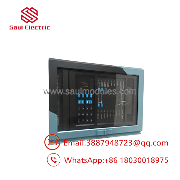
- SR750-P1-G1-S1-HI-A20-R-E-H
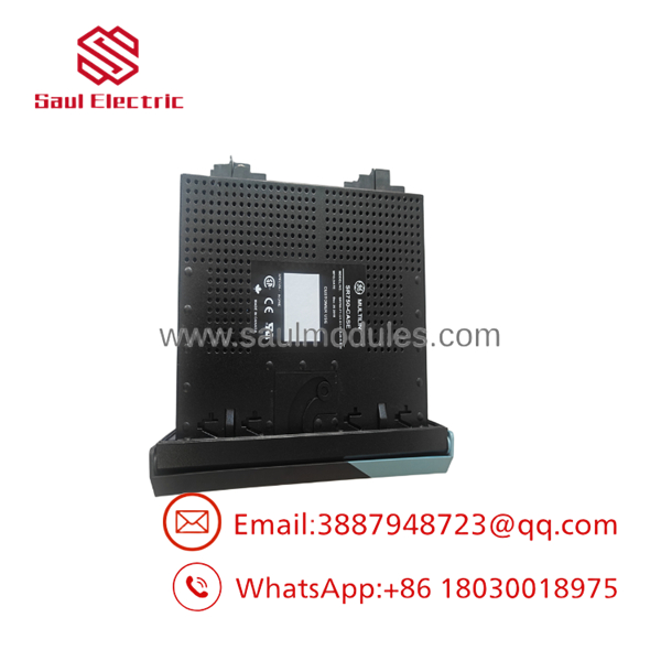
- -P1-G1-S1-HI-A20-R-E-H
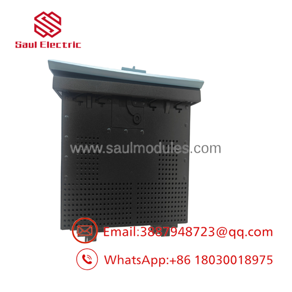
- -P1-G1-S1-HI-A20-R-E-H
Transparency SOP: Quality Assurance & Testing
We don’t just ship boxes; we test them on actual GE Multilin protection equipment whenever practical.
- Inbound Inspection
- Verify complete ordering code and serial number.
- Inspect LCD, keypad, connectors, and drawout mechanism.
- Confirm conformal coating integrity.
- Screen for counterfeit or repaired assemblies.
- Live Rig Testing
- Apply rated control power.
- Verify startup diagnostics.
- Test relay outputs and digital inputs.
- Confirm Ethernet and serial communications.
- Verify self-test results.
- Electrical Parameter Checks
- Measure control power consumption.
- Verify analog output accuracy.
- Test CT input channels.
- Confirm relay pickup and dropout characteristics.
- Firmware Verification
- Record firmware revision.
- Verify hardware revision.
- Confirm EnerVista connectivity.
- Final QC & Packaging
- Anti-static packaging.
- Protective foam and shock-resistant packing.
- Final functional inspection.
- Serial number traceability.
The Veteran’s Tech Trap Guide
⚠️ Export the settings before touching the relay.
Protection coordination depends on pickup values, time-current curves, FlexLogic equations, breaker failure timers, and communication parameters. Losing those settings can turn a simple replacement into an all-day commissioning job.
❗ Don’t confuse 1 A and 5 A CT versions.
This relay is configured for 1 A CT secondary circuits (P1). Installing it on a feeder wired for 5 A CTs without changing the hardware will produce incorrect current measurements and unreliable protection.
⚠️ Verify the drawout case.
The relay is normally supplied as a drawout unit. The case is frequently sold separately, so confirm whether your replacement includes the fixed case or only the relay module.
❗ Check the Ethernet settings before energizing.
The “E” version supports Ethernet communications. Duplicate IP addresses or outdated network parameters can look like relay failures even though the hardware is operating correctly.
Frequently Asked Questions (FAQ)
Q1. What does P1-G1-S1-HI-A20-R-E-H mean?
- P1 – 1 A phase CT inputs
- G1 – 1 A zero-sequence CT input
- S1 – 1 A sensitive ground CT input
- HI – 88–300 VDC / 70–265 VAC control power
- A20 – Eight 4–20 mA analog outputs
- R – Red breaker-closed LED
- E – Enhanced display with integrated Ethernet
- H – Factory conformal coating for harsh environments
Q2. Does this relay support Ethernet?
Yes. The E option includes an integrated 10Base-T Ethernet interface, in addition to RS-232, RS-422, and RS-485 communication ports. It supports integration with EnerVista software and common industrial communication architectures.
Q3. Is the relay hot-swappable?
No. Although the relay uses a drawout design, replacement should only be performed after isolating the protected feeder and following plant lockout/tagout procedures.
Q4. Is the case included?
Not necessarily. Many surplus suppliers sell only the relay. Confirm whether the drawout case is included if a complete assembly is required.
Q5. Why choose the -H version?
The H option provides a conformal-coated PCB that offers additional protection against humidity, conductive dust, salt spray, and corrosive atmospheres. It is commonly specified for offshore facilities, coastal plants, mining operations, and chemical processing environments.
Q6. Why are surplus units less expensive than buying directly from the OEM?
Most available inventory comes from utility upgrades, canceled capital projects, or strategic spare-part reductions. Lower pricing reflects the secondary supply chain rather than reduced functionality. Every relay should still undergo functional testing before shipment.
Q7. What warranty is typically available?
Professionally tested surplus or refurbished units are commonly supplied with a 12-month warranty covering functional defects under normal operating conditions. Damage caused by incorrect wiring, overvoltage, unauthorized modifications, or electrostatic discharge (ESD) is generally excluded.
Engineering Note:fore commissioning an , save the complete EnerVista configuration file, document CT ratios, feeder protection settings, FlexLogic equations, Ethernet parameters, and event recorder configuration. Replacing the hardware usually takes less than 30 minutes. Rebuilding a lost protection scheme from memory can take an entire shift.


 Start Chat


