





Description
Key Technical Specifications
| Parameter | Specification Value |
| Module Slot Platform | Form-factor card for Slot 7 (Comms) of GE UR Chassis |
| Optical Interfaces | 2x Independent Transceiver Channels |
| Laser Transmitter Wavelength | 1300 nm nominal |
| Fiber Media Type | Single-mode fiber optic cable |
| Processor Capability | 1.3 GHz processing support mapped via main relay CPU |
| Network Protocol Architecture | IEC 61850, Modbus TCP/IP, DNP 3.0 Level 2, IEC 60870-5-104 |
| Protection-Grade Telemetry | High-speed peer-to-peer messaging & Routable GOOSE (R-GOOSE) |
| Diagnostic Configuration | Real-time channel attenuation monitoring & health trending via EnerVista |
| Typical Distance Link | Long-haul substation-to-substation peer link profiles |
| Operating Temperature | −20 to +60°C |
| Storage Temperature | −40 to +85°C |
| Cooling Method | Passive natural convection through modular relay chassis venting |
| Physical Weight | Approximately 0.85 lbs (0.38 kg) |
Product Introduction
The GE Multilin UR-7KH is a high-performance, modular optical communications card designed explicitly for the Universal Relay (UR) and URPlus protection and control platform. Engineered for installation directly into the dedicated communications module slot of the UR chassis, this card enables rapid, deterministic peer-to-peer telemetry between protective relays. By utilizing high-speed optical data paths, the UR-7KH replaces expensive, noise-sensitive copper hardwiring across substations, providing an immune infrastructure against electromagnetic interference (EMI) and ground potential rise.
The distinct “7KH” specification signifies a dual-channel 1300 nm single-mode LASER module layout. This configuration is tailored for long-distance, high-reliability inter-relay protection schemes—such as line differential protection (L90), high-impedance busbar setups (B30), or wide-area coordinated tripping networks. Capable of routing critical IEC 61850 GOOSE and R-GOOSE messages directly over single-mode fiber infrastructure, it provides the low-latency communications backbone necessary for high-speed protective tripping applications.
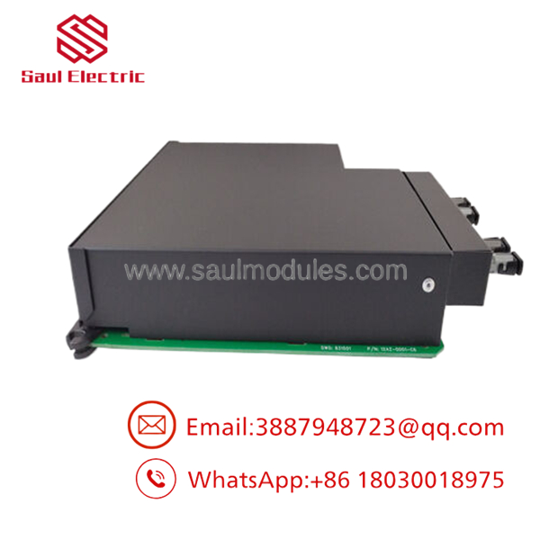
- UR7KH
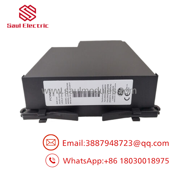
- UR7KH
Installation & Configuration Guide
Stage 1: Pre-Installation Preparation (Estimated Time: 15 minutes)
- ⚠️ Safety First: Completely de-energize the host Universal Relay chassis by pulling the main power supply terminal blocks or opening the DC control battery knife switches. Working on an energized UR backplane poses severe risk of structural damage to adjacent CPU and I/O cards. Isolate current transformer (CT) links via local shorting blocks if any current modules share the backplane rail.
- Tools Required: Grounded ESD wrist strap, clean fiber optic inspection scope, lint-free fiber cleaning swaps, isopropyl alcohol (>99% purity), and a small flathead screwdriver for module retention locks.
- Data Backup: Connect a laptop to the front RS232 or USB port of the relay using EnerVista UR Setup software. Backup the full relay configuration archive (
.ursparameter map) to preserve device settings and automated FlexLogic profiles.
Stage 2: Removing the Old Module (Estimated Time: 5 minutes)
- Verify the chassis is unpowered and the ESD wrist strap is snapped to the station ground bar.
- Carefully unlatch the protective fiber optic cable connectors from the TX/RX ports. Immediately install protective dust caps onto both the fiber ends and the module optical ports.
- Loosen the upper and lower captive retaining screws on the module’s metal faceplate.
- Grasp the pull-tabs on the module faceplate and draw the card straight out of the slot channels. Avoid tilting the module to protect the multi-pin backplane card-edge connectors.
Stage 3: Installing the New Module (Estimated Time: 10 minutes)
- Remove the new UR-7KH from its anti-static shielding jacket while maintaining solid ESD grounding.
- Align the module’s circuit board edges with the guide tracks in the relay chassis communications slot (Slot 7).
- Slide the card smoothly inward until the front plate meets the chassis edge, then apply firm, balanced pressure to fully seat the backplane pins into the mother-board receptacle.
- Securely tighten the upper and lower faceplate retaining screws to establish electrical ground continuity to the chassis frame.
- Fiber Cleanliness: Inspect the single-mode fiber tips under the scope. Clean away oils or airborne particulates using an alcohol swap, then click the connectors firmly into place on the 1300 nm laser ports.
❗ Configuration Check:
[ ] Backplane retaining hardware screws are firmly tightened down.
[ ] Optical fiber terminations are cleaned and matched to correct TX/RX assignments.
[ ] System configuration firmware build matches the rest of the relay hardware modules.
Stage 4: Power-On & Testing (Estimated Time: 10 minutes)
- Restore main station control power to the UR chassis.
- Observe the front screen diagnostic sequence. The main unit should boot without a “Module Mismatch” or “Hardware Error” flag.
- Open the EnerVista UR software utility and check the Module Status registers. Verify the card in Slot 7 is recognized correctly as a UR-7KH.
- Check actual values for the optical channels: Confirm loop status registers show active link status with valid optical power level measurements within nominal dB attenuation specs.
Strategic Quality Control & Inspection Process
Because communications stability is the single most critical factor in multi-terminal protection schemes, our surplus and reconditioned UR-7KH modules pass through a rigorous, multi-point validation protocol.
- Inbound Inspection & Visual Micro-Audit: Serial arrays are mapped to trace provenance. Every board undergoes microscopic verification to detect card-edge contact friction scoring, circuit tracking fatigue, hairline solder cracks, or port alignment variations.
- Optical Power & Wavelength Diagnostics: The card is powered on a laboratory test bed. We utilize an optical power meter and spectrum analyzer to ensure the dual 1300 nm laser transmitters generate optimal output levels within precise OEM tolerances, verifying clean signaling across maximum rated single-mode fiber run thresholds.
- Live Substation Simulator Stress Profile: The module is slid into a reference Universal Relay chassis hooked into a multi-node network rig. We stress-test the interface by injecting heavy traffic blocks—simulating real-world protection scenarios using IEC 61850 GOOSE cross-tripping arrays—and monitor for frame drops or transmission latency over a 24-hour testing cycle.
- Firmware Synchronicity Verification: Internal interface chip builds are documented to match required module revisions. The hardware settings are restored back to factory reference configurations to ensure immediate, conflict-free pairing with your existing site CPU cards.
- Static-Shield Enclosure & Dispatch Protection: Upon final inspection sign-off, the module ports are sealed with protective dust covers. The card is enclosed within specialized ESD-safe wrap, surrounded by high-density protective foam block structures, and placed in a reinforced shipping package with its validated technical test certificate.
Frequently Asked Questions
Can the UR-7KH module be hot-swapped while the Universal Relay is operational?
No. The Universal Relay platform does not support live hot-swapping of internal backplane communication or I/O modules. Removing or inserting the card while control power is applied to the chassis can cause voltage spikes on the backplane data lines, risking irreversible damage to the card components and the main CPU module. Always kill all control power before replacing an internal module.
What is the mechanical difference between a UR-7KH and a UR-7HH module?
The core distinction lies in the specific laser transmitter configuration and target optical fiber media type. The UR-7HH variant is designed for short-range links using 820 nm or 850 nm wavelengths over multi-mode fiber infrastructure. The UR-7KH module features 1300 nm single-mode laser transceivers, optimized for longer-distance inter-relay data transmission across expansive substations or between separate facility locations.
My relay displays a “Module Mismatch” error after installing this card. How do I clear it?
A “Module Mismatch” error occurs when the hardware module installed in a slot does not match the hardware map programmed in the relay’s current configuration file. To resolve this, open your setting profile in EnerVista UR software, navigate to the Hardware Configuration layout, update Slot 7 to reflect the newly installed UR-7KH card, and download the updated configuration file back into the relay.
Will replacing this card affect the protection setpoints stored inside the relay?
No. The relay’s primary protection parameters, overcurrent trip curves, and custom FlexLogic equations are stored inside non-volatile memory located directly on the main CPU module card. Replacing the Slot 7 communications module only alters the physical interface path for network traffic. However, you must verify that any communication mapping parameters specific to the link are re-confirmed after installation.
Why use a new surplus UR-7KH module instead of purchasing a completely modern alternative platform?
Upgrading a critical protection node to an entirely new relay family requires significant engineering investments, including rewriting protection logic, modifying physical wiring schematics, updating cabinet layouts, and re-validating SCADA network maps. Sourcing a genuine surplus UR-7KH module allows you to repair the existing relay chassis in under 30 minutes, maintaining full system functionality with zero downstream engineering overhead. Every module comes backed by our comprehensive 1-year replacement warranty.


 Start Chat


