





Description
Key Technical Specifications
| Parameter | Value |
|---|---|
| Manufacturer | GE Multilin |
| Model | UR8LH (UR-8LH) |
| Product Type | CT/VT Input Module |
| Series | UR Universal Relay |
| Current Inputs | 4 CT inputs |
| Voltage Inputs | 4 VT inputs |
| Function | Analog current and voltage acquisition |
| Diagnostics | Enhanced analog signal diagnostics |
| Configuration | EnerVista™ UR Software |
| Installation | Plug-in module inside UR relay chassis |
| Compatibility | GE Multilin UR Universal Relay platform |
| Approximate Weight | 1.2 kg |
| Typical Applications | Generator, Transformer, Feeder, Bus, Motor Protection |
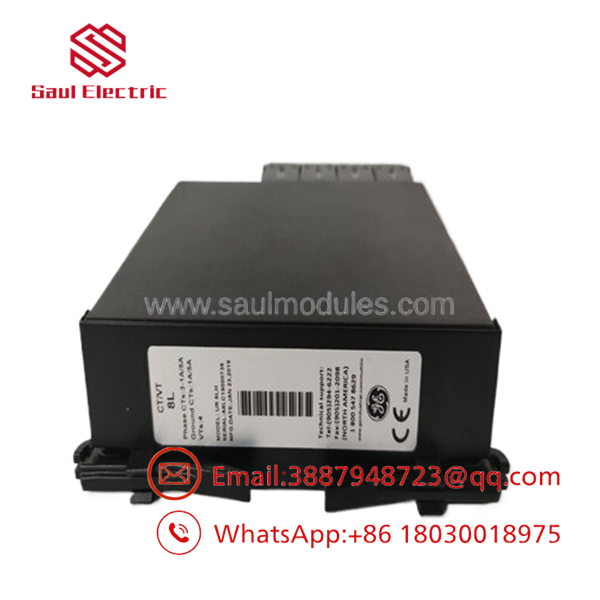
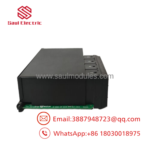
The UR8LH is a CT/VT measurement module for the GE Multilin UR Universal Relay family. It provides 4 current transformer (CT) and 4 voltage transformer (VT) inputs while incorporating enhanced diagnostics to verify analog signal integrity and improve protection reliability.
Product Introduction
The GE UR8LH is a CT/VT analog input module designed for the GE Multilin UR Universal Relay platform. Installed inside the relay chassis, it converts field current and voltage transformer signals into precision analog measurements used by the relay’s protection, control, metering, and monitoring functions. The module serves as the primary measurement interface for generator, transformer, feeder, motor, and bus protection applications.
The UR8LH supports 4 CT inputs and 4 VT inputs and incorporates enhanced diagnostic algorithms that continuously monitor analog signal integrity. Measured values are available through the relay front display or EnerVista™ UR software, allowing engineers to configure, monitor, and troubleshoot protection systems efficiently. GE recommends matching the module with compatible CPU hardware to avoid hardware compatibility issues in newer UR relay revisions.
Troubleshooting Quick Reference
| Symptom | Possible Cause | Relevance | Quick Check | Recommendation |
|---|---|---|---|---|
| No current measurements | CT secondary wiring open | ✅ High | Measure CT secondary continuity | Verify CT wiring before replacing the module |
| Incorrect voltage readings | VT wiring or ratio configuration error | ✅ High | Compare VT secondary voltage with relay display | Check VT wiring and settings |
| Analog input diagnostic alarm | CT/VT signal integrity fault | ✅ High | Review relay diagnostics in EnerVista | Inspect field transformers and wiring |
| Relay reports hardware mismatch | Incompatible CPU or module revision | ✅ High | Verify relay hardware configuration | Install compatible module/CPU combination |
| Unstable measurements | Loose terminal connections or electrical noise | ⚠️ Medium | Inspect CT/VT terminals and grounding | Tighten connections and improve shielding |
| Module not detected | Improper installation or connector issue | ✅ High | Reseat the module and inspect connectors | Reinstall module and verify chassis compatibility |
Field Tip: Most UR8LH issues originate from CT polarity errors, open CT circuits, incorrect VT ratios, or hardware compatibility rather than module failure. Before replacing the module, save the relay configuration, verify CT/VT wiring, inspect analog diagnostics, and confirm the installed CPU revision.
- UR8LH
Frequently Asked Questions (FAQ)
Q1. What is the primary function of the ?
The is a CT/VT analog input module that supplies the UR Universal Relay with current and voltage measurements required for protection, control, metering, and monitoring functions.
Q2. How many analog inputs does the provide?
The module provides 4 Current Transformer (CT) inputs and 4 Voltage Transformer (VT) inputs, enabling accurate acquisition of electrical system measurements.
Q3. Which relays are compatible with the ?
The is designed for the GE Multilin UR Universal Relay family and is used in protection applications for generators, transformers, feeders, motors, and bus systems.
Q4. Can the be replaced while the relay is energized?
No. The is not hot-swappable. Remove all control power and follow ESD precautions before installing or replacing the module to prevent equipment damage.
Q5. Is this product supplied as new or refurbished?
Unless otherwise specified, this listing refers to New Original (New Surplus) inventory. Every module should undergo visual inspection, identification verification, connector inspection, and ESD-safe packaging before shipment.
Q6. What quality inspections should be completed before shipment?
Recommended quality inspections include:
- OEM part number verification
- Visual inspection for physical damage or corrosion
- Connector and PCB inspection
- CT/VT input verification
- Hardware compatibility verification
- ESD-safe packaging with QC documentation
Q7. What is the most common installation mistake?
The most common mistake is installing the with an incompatible CPU revision or incorrect CT/VT wiring configuration. Before replacement, back up the relay configuration, verify CT polarity and VT ratios, and ensure the relay hardware revision supports the installed module. This helps prevent hardware mismatch alarms and inaccurate measurements.



 Start Chat


