





Description
Key Technical Specifications
| Parameter | Value / Specification |
|---|---|
| System Architecture | Standard 6U VMEbus Framework (VME64 compatible) |
| Functional Name | VME-PMC-CADDY (PMC Caddy / Carrier Board) |
| Mezzanine Standard | Compliant with IEEE P1386 / draft 2.0 |
| Slot Capacity | Accommodates 2 Single-Size PMCs OR 1 Double-Size PMC |
| Onboard Bridge Controller | Tundra Universe II (CA91C042) VME-to-PCI Bridge |
| PCI Local Bus Spec | 32-bit Data Path running at 33 MHz clock frequency |
| Rear Signal Routing | All PMC I/O lines map directly to VMEbus P2 rows A, B, and C |
| Alternative Signal Map | Option -32P2 variant provides custom P2 pin-out assignments |
| Operating Voltages | Powered directly from VME backplane (+5V, +12V, -12V rails) |
| Board Protection | High-grade industrial conformal coating layer |
| Operating Temp | 0 to +65°C (32 to 149°F) standard industrial environment |
Product Introduction
The GE VME-PMC-CADDY is a rugged 6U VMEbus carrier card designed to bridge custom physical networks by adapting modular PCI Mezzanine Cards (PMCs) into standard industrial VMEbus rack enclosures. Originally engineered by esd electronics and integrated into complex automation platforms by GE Fanuc, GE Power, and Abaco Systems, this card acts as a mechanical and electrical adapter. It allows plant engineers to mix and match modular industrial network cards (such as CAN bus interfaces, reflective memory links, high-speed fiber-optic components, or custom FPGA array blocks) without redesigning the primary single-board computer framework.
At the heart of the VME-PMC-CADDY is the high-performance Tundra Universe II (CA91C042) VME-to-PCI bridge chip. This silicon engine translates deterministic VME rack commands into local 32-bit/33MHz PCI bus data frames. The “Caddy” provides flexible mounting capacity, accepting either two distinct single-size PMC cards or a single large double-width mezzanine card. For high-availability defense, aerospace, and HILS (Hardware-in-the-Loop Simulation) configurations, all mezzanine I/O lines are mapped seamlessly to the VME P2 rear connector pins, enabling effortless rear transition patching.
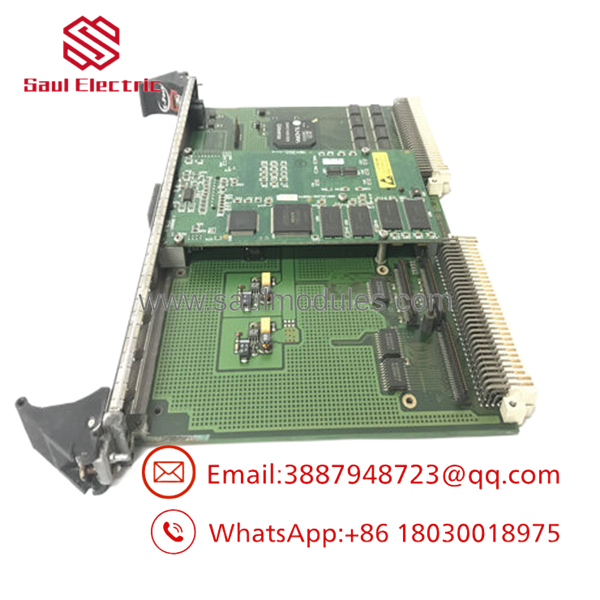
- VME-PMC-CADDY
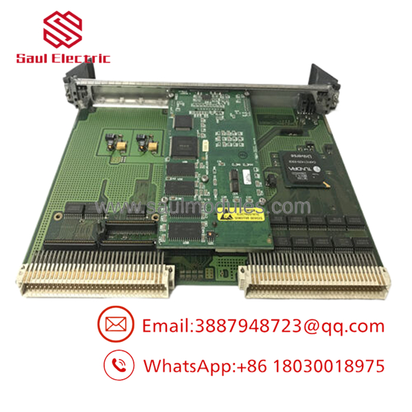
- VME-PMC-CADDY
Installation & Configuration Guide
Stage 1: Pre-Installation Preparation (Estimated Time: 20 minutes)
- ⚠️ Safety First: The VME-PMC-CADDY acts as an active logic bridge on the VME data highway. Never insert or pull this carrier card or its attached PMC modules while the VME backplane power is turned on. Shut down the process completely, isolate power lines, and execute a full lock out/tag out (LOTO) on the master rack control circuit breaker.
- Tools Required: Grounded anti-static wrist strap, small Phillips screwdriver, fine slot tool, needle-nose placement pliers, laptop with your VME development software suite (VxWorks, Linux, or custom OS utilities).
- Data Backup: Document the exact positioning of any physical configuration jumpers on the PMC sub-modules before installation. Note the specific memory-mapped base addresses and interrupt vectors required by your system platform configuration files.
Stage 2: Mounting PMC Modules to the Caddy (Estimated Time: 10 minutes)
- Affix your anti-static wrist strap to a verified grounding pad on your electronics workbench. Do not handle the modules in a high-static environment.
- Remove the blank filler panel from the front bezel of the VME-PMC-CADDY slot where your PMC will reside.
- Slide the front bezel of the PMC module into the open window from the component side of the carrier board.
- Align the dual high-density multi-pin plug sockets on the bottom of the PMC module with the mating headers on the CADDY board. Press down firmly and evenly until the connectors seat completely flush.
- Turn the carrier assembly over and secure the PMC card to the mechanical standoffs using the factory-provided low-profile retention screws.
Stage 3: Inserting the Assembled Carrier Board (Estimated Time: 10 minutes)
- Verify that all rear backplane connectors on the VME-PMC-CADDY are free of dust, lint, or bent pins.
- Open the upper and lower injector/ejector handles on the front faceplate of the VME card cage slot.
- Guide the edges of the carrier board into the track channels of the targeted single-slot VME subrack position.
- Push the card smoothly inward until the ejector handles meet the frame lip.
- Snnap both ejector handles inward simultaneously to lock the backplane connectors firmly into the rack socket. Tighten the faceplate thumbscrews to secure the assembly against vibrations.
Stage 4: Power-On & Initialization Diagnostics (Estimated Time: 15 minutes)
- Re-energize the main control breaker to apply power to the VME rack backplane.
- Observe the initial power-up indicators: The primary rack status LEDs should illuminate green, and the link status lights on the front of your attached PMC modules should show initial activity.
- Boot up your target real-time operating system (RTOS) console workspace.
- Bus Discovery Check: Run a standard system hardware scan (such as a PCI bus discovery command) to verify that the Tundra Universe II bridge is recognized by your kernel.
- Confirm that the system correctly enumerates the Vendor ID and Device ID codes of the nested PMC modules before initializing automated data acquisition processes.
Frequently Asked Questions (FAQ)
Can I hot-swap individual PMC modules while the carrier card is inside a powered VME rack?
Absolutely not. The local PCI bus on the VME-PMC-CADDY does not incorporate voltage isolation circuitry for live insertions. Attempting to install or remove an attached mezzanine card while the VME backplane is energized will trigger logic shorts, corrupt systemic data frames across the shared VME data bus, and cause permanent thermal failure to both the carrier board and the expensive PMC sub-modules.
What is the operational difference between the standard Caddy and the “-32P2” model variant?
The standard version of the carrier routes all I/O traces coming off the PMC mezzanine boards directly to rows A, B, and C of the standard VME P2 rear connector in a standard factory sequence. The specialized -32P2 model provides a distinct, altered pin-assignment mapping across the P2 backplane row architecture. This is designed for legacy system compatibility or custom military/industrial wiring backplanes that require isolated routing layers.
Why does my real-time operating system fail to detect the PMC module during startup?
This issue is typically caused by one of two factors: either the VME-PMC-CADDY card is not pushed deep enough into the backplane to establish solid contact on the rear pins, or your OS kernel lacks the driver package for the Tundra Universe II bridge controller. First, check that the front ejector handles are fully closed and locked. Next, ensure your operating system image includes the necessary Universe II PCI-to-VME bridge initialization parameters.
Does this carrier board impose any performance constraints or signal delays on the PMC modules?
No, the VME-PMC-CADDY maintains the full native 32-bit data bandwidth and 33 MHz bus speed specified for the local PMC mezzanine slots. The Tundra Universe II bridge chip coordinates ultra-fast hardware-level data translation. This ensures that high-speed communication cards, such as reflective memory modules or CAN interfaces, can run at their maximum rated processing speeds with negligible arbitration latency.
How are these legacy carrier boards supplied now that they are out of active production?
Because legacy 6U VME industrial platforms have transitioned to newer architectures like VPX, these specific carrier units are generally supplied from New Original / New Surplus or refurbished warehouse spares. These are unused, pristine factory parts sourced directly from decommissioned project reserves, canceled simulation infrastructure builds, or industrial liquidations, allowing you to maintain your active control systems without carrying out costly re-engineering overhauls.



 Start Chat


