





Description
Key Technical Specifications
| Parameter | Specification / Value |
| Processor Architecture | Intel Pentium III (Coppermine) running at 850 MHz |
| L2 Cache Capacity | 256 KB advanced transfer cache running at full processor speed |
| System Memory | 512 MB PC100/PC133 SDRAM via standard 144-pin SODIMM |
| Form Factor | 6U single-slot standard VMEbus configuration |
| Onboard Flash Storage | Up to 1 GB CompactFlash capability via secondary IDE controller |
| Front Panel Interfaces | 2 × 10/100Base-TX Ethernet (RJ45), 2 × RS232 Serial (DB9), 1 × USB 1.1, 1 × VGA output, 1 × PS/2 Keyboard/Mouse |
| Backplane Routing | P1 and P2 Eurocard style mappings for custom rear transition module usage |
| Expansion Interface | One 32-bit/33 MHz PCI Mezzanine Card (PMC) site (IEEE 1386.1 compliant) |
| Non-Volatile SRAM | 32 KB battery-backed NVRAM for system operational log persistence |
| Bus Controller Engine | Universe II PCI-to-VME bridge controller chip |
| Power Requirements | +5 VDC (±5%), ~2.8 A typical / 3.4 A maximum |
| Operating Temperature | 0°C to +55°C (32°F to 131°F) under continuous airflow |
| Physical Dimensions | 233.4 mm H × 160.0 mm D × 20.3 mm T (9.2 × 6.3 × 0.8 inches) |
Product Introduction
The GE Fanuc / VMIC VME7740-841 is an industrial 6U VME Single Board Computer designed for deterministic computation in real-time processing, manufacturing automation, and legacy SCADA systems. Driven by an 850 MHz Intel Pentium III processor and the Universe II PCI-to-VME bridge, this processor board ensures fast, low-latency communication across the VMEbus backplane architecture.
This layout features 512 MB of onboard SDRAM and includes an integrated PMC expansion slot for custom system add-ons like high-speed fieldbus interfaces or digital I/O arrays. With integrated VGA video, dual Fast Ethernet, and twin front-panel RS232 ports, the VME7740-841 operates as a self-contained automation hub. It manages local human-machine interfaces and processes incoming telemetry loops without taking up extra chassis space.
【Core Strategy 1: SOP Quality Transparency】
Because old computing modules face component aging and capacitor wear, all VME7740-841 boards undergo strict diagnostic protocols to verify original performance before shipment.
1. Inbound Inspection & Traceability
- Hardware Validation: Serial stamps and board revisions are cross-referenced with VMIC / GE Fanuc engineering documents to confirm standard parts tracking.
- Component Surface Screening: The multi-layer board is scanned under magnification to check for aging trace paths, electrolyte leakage on capacitors, or micro-cracks around the BGA processor chips.
- Connector Integrity Check: Backplane connection pins (P1 and P2) are inspected using specialized tools to ensure they are true, straight, and show no signs of micro-corrosion.
2. Live Functional Testing
- Test Rack System: The VME7740-841 board is seated into a functional 6U VMEbus enclosure powered by an independent auxiliary power station.
- BIOS POST Diagnostics: The processor card must clear its complete Power-On Self-Test routine, proving the core memory registers, IDE interfaces, and PCI buses initialize cleanly.
- Real-Time OS Evaluation: Technicians load target platforms like VxWorks or Windows NT/2000 Embedded. The board is run under processing loads for 12 hours to verify system stability under heavy processing threads.
- Interface Verification: Physical validation routines check communication performance across both front-panel Fast Ethernet ports, the VGA video link, and both serial loops.
3. Electrical Parameter Testing
- Power Draw Analysis: Steady-state current consumption on the +5 VDC rail is monitored to confirm it stays within the factory 3.4 A upper limit.
- Dielectric Isolation Audits: The ground plane paths are verified to keep any electrical noise isolated from the backplane signals.
4. Firmware & Configuration Verification
- BIOS Configuration Setup: System settings are reset to standard parameters, ensuring the onboard flash or IDE components boot in the correct sequence.
- Hardware Jumper Auditing: The onboard physical configuration jumpers are verified against factory specifications for base address mapping and system controller status.
5. Final QC & Packaging
- ESD Guard Shielding: Cleaned boards are packed into multi-layer static shielding bags inside an ESD-safe workspace.
- Transit Shock Protection: The packed assembly is surrounded by high-density custom foam contours inside a double-wall corrugated shipping container. A signed and dated QC Passed certification label is placed over the box seal.
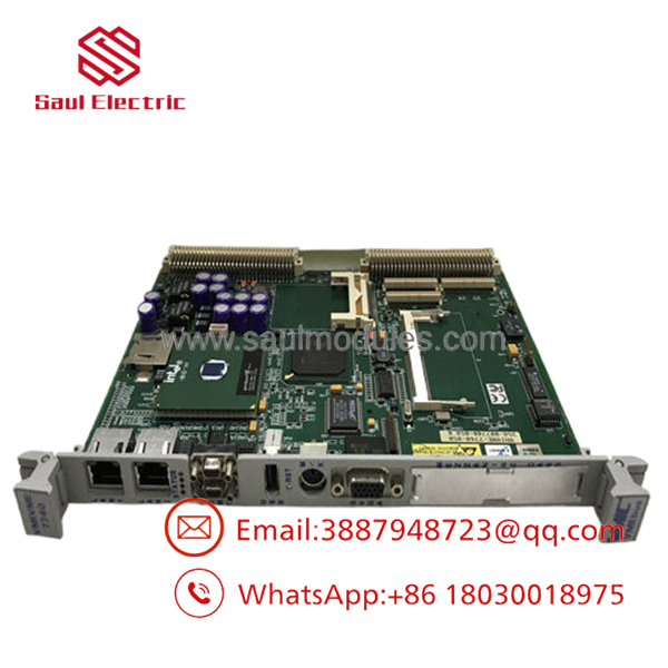
- VME7740-841
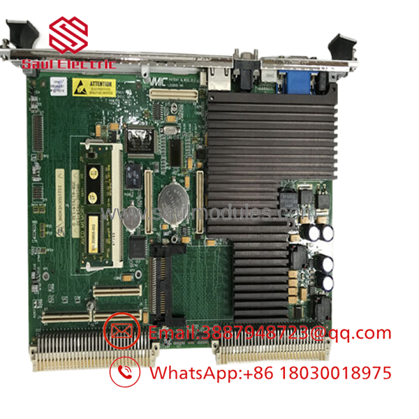
- VME7740-841
Installation & Configuration Guide
Stage 1: Pre-Installation Preparation
- Estimated Time: 15 minutes
- ⚠️ Safety First: Shut down the main VME enclosure. Turn off the primary power feeds to the sub-rack assembly. Lock out the main breaker. Wait 3 minutes to let the internal power supply capacitors release their charge completely.
- Tools Required: Grounded ESD wrist link, anti-static work pad, a fine flat-head screwdriver, and a #1 Phillips screwdriver for the PMC card mounting hardware.
- Settings Backup: If the old board can still boot, connect a serial terminal to COM1, enter the BIOS setup screen, and record all customized drive parameters, IRQ maps, and VME base window addresses.
Stage 2: Removing the Old Module
- Estimated Time: 10 minutes
- Steps:
- Secure your ESD wrist strap to an unpainted, grounded structural bar on the system rack frame.
- Unplug all front cables, including Ethernet lines, VGA video monitors, and serial connections.
- Release the upper and lower injector/ejector handles on the board face by pulling them outward to unseat the module.
- Slide the board slowly out along the chassis guide rails, keeping it flat to avoid touching or scratching adjacent cards.
- Place the pulled card directly onto a static-shielding work surface.
Stage 3: Installing the New Module
- Estimated Time: 15 minutes
- Steps:
- Verify the replacement part numbers and revision markings match the original specification.
- If the application uses a custom PMC mezzanine card, attach it to the onboard site using the correct standoff screws before installing the main board.
- Double-check all physical jumpers against your baseline record to ensure proper boot device priorities and system controller configurations.
- Align the board edges with the target slot tracks inside the 6U rack. Slide the module inward until the injector/ejector handles touch the chassis lip.
- Push both handles inward simultaneously to seat the P1/P2 connector pins firmly into the backplane socket, then tighten the captive faceplate retention screws.
- Self-Checklist:
- [ ] Front ejector tabs completely latched flat.
- [ ] Retaining screws hand-tightened to the structural frame rails.
- [ ] Optional PMC hardware aligned and fixed in place.
Stage 4: Power-On & Testing
- Estimated Time: 20 minutes
- Power-On Steps:
- Re-apply electrical power to the main VME enclosure.
- Verify that the front-panel power and status indicators turn on and that a steady BIOS display output appears on your monitoring screen.
- Press
DELduring boot-up to open the core configuration system. Confirm the BIOS recognizes the full 512 MB SDRAM array and your active storage devices. - Boot the target operating system (e.g., VxWorks, Linux, or Windows NT).
- Review the system logs to confirm that all communication links are up and that the Universe II bridge registers correctly on the bus network.
- ⚠️ Troubleshooting Note: If the board fails to clear its POST checks or resets unexpectedly, check that the P1 and P2 connections are fully seated. Loose backplane seating can cause voltage drops on the primary +5 VDC line.
【Core Strategy 2: Technical Pitfall & Survival Guide】
1. Thermal Management and Fan Failure Pitfalls
The 850 MHz Pentium III processor on the runs significantly hotter than older, low-power processors. ❗ Operating this module without sufficient forced-air cooling will lead to sudden thermal shutdowns or calculation errors. The board requires a minimum of 300 LFM of continuous airflow across its onboard heatsink. If your rack’s fan trays are old, dirty, or failing, the CPU temperature can exceed its +55°C operational limit under heavy load. Always check and clean your fan assemblies before deploying this card.
2. Battery Drain and BIOS Reset Issues
Because these modules have been out of factory production for years, the onboard NVRAM backup batteries on surplus stock may be near the end of their lifespan. If this battery drains completely, the system will lose its custom BIOS parameters and VME window settings whenever control power is removed. The board will then reset to factory defaults on the next boot, which can cause communication errors on specialized networks. Always test the battery voltage before installation, or save your custom BIOS profiles so they can be reloaded quickly if needed.
3. VME System Controller Jumper Conflicts
The has physical jumpers that determine if the card acts as the primary System Controller (Slot 1 functions, like driving the system clock and managing bus lines). If you configure this card as a System Controller while another card in the same rack already performs that function, the resulting bus arbitration conflict will freeze data traffic across the entire VME backplane. Always match the hardware jumper settings of your replacement board to the layout of the old module.
4. CompactFlash Card Compatibility Traps
The secondary IDE channel on this board uses a standard CompactFlash slot for solid-state storage. However, older industrial motherboards can be sensitive to the formatting, cylinder allocation, and speed ratings of newer CF cards. Using standard consumer-grade flash memory cards often leads to intermittent boot failures or data corruption under heavy read/write cycles. Always use high-quality, industrial-grade CompactFlash media that supports Fixed Disk Mode to ensure consistent boot reliability.
5. Backplane Connector Wear and Pin Damage
The 6U VME form factor uses high-density multi-pin arrays to route system data. If a module is inserted at an angle or forced into a slot with worn guide rails, these pins can bend or break. ❗ Never force the module into the slot. If the card does not slide completely flush with the external framework under gentle pressure, pull it out and inspect the pins using a flashlight. Repairing a damaged backplane requires completely dismantling the relay chassis.
Frequently Asked Questions (FAQ)
Can I hothe module while the rack is powered up?
No. The standard VMEbus architecture used on the platform does not support hot-swapping for primary single board computers. Pulling or inserting this card while the backplane is energized will disrupt bus timing signals, generate electrical noise on the data lines, and potentially cause data corruption or physical component damage across other modules in the rack. Always turn off the enclosure power supply before extracting the board.
What is the exact purpose of the Universe II chip on this processor board?
The Tundra Universe II chip functions as the primary PCI-to-VME bridge. It translates standard high-speed internal PCI bus signals from the Pentium III processor environment into standard VMEbus protocols. This allows your operating system to read and write data across the backplane to older I/O cards, memory modules, and communication interfaces without needing custom, non-standard driver software.
My application runs an older version of VxWorks. Will it work on this board?
the has broad native support for real-time operating systems like VxWorks (typically versions 5.4 through 6.x) and Windows NT Embedded. However, because different hardware configurations use distinct chipsets, you must verify that your operating system boot image includes the correct Board Support Package (BSP) for the VMIVME-7740 architecture.
Why does my replacement card power up but fail to recognize the connected VGA monitor?
First, check the position of your onboard video selection jumpers. The allows you to route video signals either to the front-panel high-density VGA connector or out through the rear P2 pins to a transition module. If the jumpers are set to route video to the rear, the front VGA port will remain dark even if the board boots normally.
Can I expand the system memory beyond the pre-installed 512 MB SDRAM?
The system architecture of the platform can support up to 1 GB of memory using its 144-pin SODIMM slot. However, this specific 841 configuration is optimized for a 512 MB memory limit. If your application requires an upgrade to a full 1 GB array, you must ensure the new SODIMM chip uses low-density, industrial-grade PC100/PC133 tracking specifications that match the timing constraints of the Intel chipset.



 Start Chat


