





Description
Key Technical Specifications
| Parameter | Specification Value |
| Data Transfer Performance | 2.0 Gb/s to 2.125 Gb/s continuous serial transfer speed |
| Fiber Base Configuration | 8x Multimode SFP pluggable transceiver channels pre-populated |
| Maximum Cascaded Scale | Supports up to 256 individual nodes via hub arrays |
| Long-Haul Reach (Single-Mode) | Upgradeable to 10 km maximum link range using alternative SFPs |
| Network Node Fault Tolerance | Automatic hard bypass based on Loss of Signal (LOS) / Sync Pattern loss |
| Signal Condition Preservation | Individual port-level optical signal regeneration (minimizes jitter & attenuation) |
| Remote Network Interface | 10Base-T Ethernet RJ45 port for Web Browser monitoring or TCP/IP socket query |
| Local Service Port | DB9 RS232 serial connection for terminal config setup (19.2 kbps max) |
| Physical Status Signaling | 3 Dedicated diagnostics LEDs per SFP port (Signal, Sync, Active status) |
| Chassis Enclosure Footprint | 19-inch 1U standard rackmount alignment (Optional tabletop conversion) |
| Primary Power Intake | Internal universal power supply (90–260 VAC, 47–63 Hz input bounds) |
| Cooling Profile | Passive structural airflow through perimeter enclosure venting |
| Net Operational Mass | Approximately 12.5 lbs (5.67 kg) with full SFP distribution |
Product Introduction
The GE Fanuc VMIACC-5595-208 (350-805595-208N) is a high-speed, managed, multi-port reflective memory fiber optic hub engineered to serve as the low-latency backbone for the VMIVME-5565 and VMIPCI-5565 real-time network infrastructure. Reflective memory networks function by mirroring hardware memory zones automatically across separate computing racks without processor handshaking overhead. This hub assembly optimizes complex star and ring-star hybrid topologies, enabling deterministic, sub-microsecond data synchronization across distributed control systems (DCS), telemetry grids, or closed-loop hardware-in-the-loop (HIL) aerospace simulation nodes.
The specific “-208” package configuration specifies that the 1U rack enclosure arrives populated with eight multimode SFP pluggable transceivers, enabling immediate cost-effective deployment across localized multi-node systems. To isolate line disturbances from taking down the entire plant network, the VMIACC-5595-208 employs a dedicated internal state machine that monitors individual port synchronization. If an asset rack fails or an optical line loses its carrier light, the port automatically bypasses the compromised link within microseconds, keeping the rest of the fiber loop online while regenerating clean, low-jitter optical signals for downstream nodes.
Installation & Configuration Guide
Stage 1: Pre-Installation Preparation (Estimated Time: 15 minutes)
- ⚠️ Safety First: Confirm the target 1U rack enclosure position is unpowered before setting the hub chassis into the rails. Do not look directly into active fiber optic cable tips or open SFP transceivers; the invisible laser emissions can cause irreversible optical damage.
- Tools Required: Grounded static wrist strap, optical fiber inspection scope, premium fiber cleaning pads, and a crosshead screwdriver for standard 19-inch rack rail screws.
- Data Backup: Connect an RS232 terminal link to the old hub unit. Execute a data dump of current control registers and port exclusion profiles via standard terminal commands to ensure matching network parameters on the replacement unit.
Stage 2: Removing the Old Hub (Estimated Time: 10 minutes)
- Isolate and disconnect the main AC universal power connector from the rear of the device.
- Label each incoming fiber optic pair with its corresponding SFP port assignment (Ports 1 through 8).
- Immediately insert protective plastic dust caps into the disconnected fiber connectors and the open SFP ports.
- Remove the four front plate rack-mount structural screws.
- Draw the 1U chassis forward out of the server rack structure and place it onto an ESD-protected clean workbench area.
Stage 3: Installing the New Hub (Estimated Time: 15 minutes)
- Don your grounded ESD wrist strap before sliding the new VMIACC-5595-208 out of its anti-static shielding bag.
- Align the unit with the vacant 1U position in the 19-inch rack frame, slide it into place, and secure it firmly via the four faceplate screws.
- Fiber Preparation: Remove dust caps and inspect the fiber optic tips under an evaluation scope. Clean away oils or micro-particles with lint-free swabs and isopropyl alcohol to prevent signal insertion loss.
- Insert the multimode fibers into the respective SFP transceivers until they click firmly into place. Ensure the transmit (TX) and receive (RX) lines cross-pair properly to your network node specifications.
- Connect your remote network monitoring infrastructure into the dedicated 10Base-T Ethernet RJ45 terminal.
❗ Configuration Check:
[ ] All populated SFP latches are fully clicked closed.
[ ] Optical cable routing radii adhere to minimum bend safety tolerances to avoid attenuation.
[ ] Front frame mounting thumbscrews are checked and tightened down.
Stage 4: Power-On & Testing (Estimated Time: 15 minutes)
- Insert the universal AC utility power lead into the rear receptacle.
- Monitor front status LEDs: The device should boot cleanly, and individual port LEDs should show green indicator light profiles when an active, synchronized reflective memory node card is initialized at the opposing end of the cable line.
- Access the internal management console through an Ethernet web browser session using the default or designated IP address.
- Verify from the system log that all bypass states are operating automatically based on Loss of Signal (LOS) thresholds and that zero frame synchronization errors are logged on the 2 Gb/s fiber matrix.
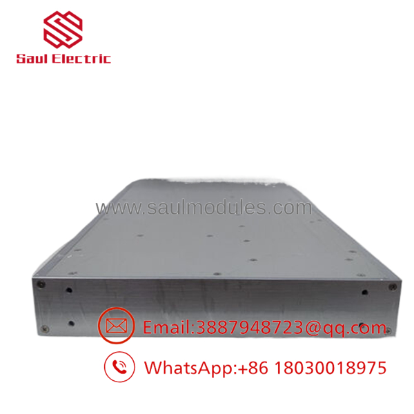
- VMIACC-5595-208 350-805595-208N
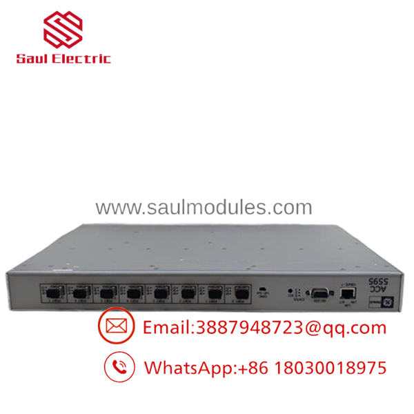
- VMIACC-5595-208 350-805595-208N
Strategic Quality Control & Inspection Process
To guarantee real-time data integrity without operational degradation, every surplus or reconditioned reflective memory hub assembly is vetted through our multi-point laboratory clearance protocol.
- Inbound Visual and Component Integrity Audit: Manufacturing part numbers are validated against known Abaco/GE engineering baselines. Units undergo inspection for enclosure deflection, port alignment deviations, motherboard traces, power supply capacitor values, and terminal degradation.
- Laser Performance and Transceiver Power Bench Testing: The hub is evaluated using an optical spectrum analyzer to verify that all 8 SFP ports operate within precise milliwatt power and wavelength tolerances. Each channel must execute stable optical generation parameters to completely eradicate signal attenuation and jitter across long lines.
- High Traffic Real-Time Comm Simulation Loop: The VMIACC-5595-208 is integrated into a multi-node 5565 reflective memory ring array alongside running host cards. We simulate heavy data bursts at full 2.125 Gb/s throughput while checking for data drops or frame distortion. During this phase, we deliberately simulate node crashes to ensure the internal state machine triggers its automatic port bypass sequence within microseconds without disrupting network traffic.
- Control Register Optimization and Master Factory Reset: IP addresses, default management login parameters, and hardware configuration flags are brought back to original factory reference states, ensuring an uncompromised setup profile when deployed at the end-user site.
- Anti-Static Enclosure and Industrial Secure Pack-out: Upon structural sign-off, every open optical node is plugged with a clean dust cap. The complete chassis is wrapped in thick, metallized static-barrier sheeting, secured in high-density foam framing blocks, and shipped within a double-walled corrugated box with its certified laboratory inspection certificate.
Frequently Asked Questions
Can I hot-swap single SFP modules while the is actively routing system data?
Yes, you can hot-swap individual SFP modules while the hub is running. Because the transceiver architecture uses independent, self-contained small form-factor interfaces, you can plug or unplug an individual module without needing to power down the primary universal supply rail. When you extract an SFP module, the internal logic automatically registers a Loss of Signal (LOS) and bypasses that channel slot, ensuring the rest of the node ring stays intact. However, note that pulling an active transceiver will immediately break communication to the specific node it serves.
What is the mechanical difference between a 350-805595-208N and other board suffixes like “E” or “J”?
The trailing letters (such as N, J, E, or H) denote internal manufacturing bill-of-materials component revisions, internal component sourcing adjustments, or specific firmware versions preloaded at the factory. The core technical capabilities—including the 2 Gb/s transport rate, port capacity, and software command sets—remain consistent. A “208N” board functions as a direct drop-in replacement for any older “208” series variant within existing 5565 network lines.
Can I mix single-mode and multimode fiber SFP transceivers on this single hub assembly?
Yes. The features a flexible architecture that supports mixed fiber configurations. Although the “-208” bundle comes standard with eight multimode SFP transceivers for local connections under 300 meters, you can pull any individual transceiver out and replace it with a single-mode 1300 nm SFP transceiver to reach an isolated node up to 10 kilometers away. The internal logic handles signal regeneration uniformly across all port profiles regardless of the fiber type.
How do I connect to the internal management system to configure the automatic bypass settings?
The configuration console can be accessed via two separate paths. For a local connection, hook a laptop to the front DB9 RS232 port with a null-modem cable and launch a terminal emulator configured for 19,200 baud, 8 data bits, 1 stop bit, and no parity. For remote configuration, connect to the RJ45 10Base-T Ethernet port and type the hub’s designated IP address into a web browser to access the web-based utility configuration panel.
Why source a new surplus hub instead of migrating to a modern industrial network standard?
Migrating a critical real-time application from specialized reflective memory to alternative architectures (like industrial Ethernet networks) involves immense engineering overhead. Standard networks rarely achieve the deterministic, zero-handshake latency provided by reflective memory, and migration requires rewriting specialized software logic, changing physical fiber runs, and repeating extensive verification cycles. Sourcing a genuine surplus hub allows you to drop the exact architectural fit back into your network in under 30 minutes, keeping your system operational with zero modification to field code or infrastructure. Every module includes our 1-year independent depot replacement warranty.

 Start Chat


