





Description
Key Technical Specifications
- Product Type: 64-bit TTL digital input/output board.
- Bus Standard: VMEbus compatible.
- I/O Width: 64 bits total, organized as eight 8-bit ports.
- Port Direction: Each 8-bit port is individually programmable.
- Fault Detection: Built-in-Test supports off-line and on-line fault detection and isolation.
- Output Drive: 64 mA sink capability.
- Transfers: Supports 8-, 16-, and 32-bit transfers.
- Connector Type: Dual 64-pin connector, DIN 41612.
- Board Size: 6U.
- Power Requirement: +5 VDC, 3 A maximum.
- Operating Temperature: 0 to 55 °C.
- Storage Temperature: -20 to 85 °C.
Product Introduction
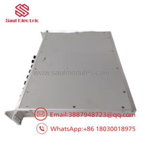
The GE VMIVME-2510B is a VMEbus-compatible 64-bit TTL digital I/O board used in industrial control, test stands, and legacy VME systems. It provides eight programmable 8-bit ports, built-in fault detection, and a front-panel fail indicator for fast diagnostics in the rack.
Engineers usually choose this board when they need a direct-fit replacement for an existing VMIC VME I/O slot without changing the host system architecture. Its built-in-test logic and separate control/data decoding make it practical for legacy maintenance work where uptime matters and spare parts are limited.
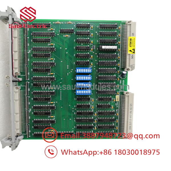
- VMIVME-2510B
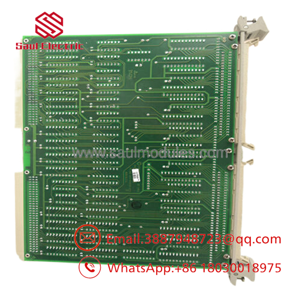
- VMIVME-2510B
Installation & Configuration Guide
Stage 1: Pre-Installation Preparation
Time estimate: 5-8 minutes.
- ⚠️ Safety First: Notify operations of downtime, verify safe state, lock out/tag out power, and wait at least 5 minutes for capacitor discharge.
- Gather tools: ESD strap, PH1 screwdriver, multimeter, wire labels, and a smartphone for photos.
- Back up site data: export running logic if applicable, document I/O mapping, record any node/address settings, and photograph terminal wiring and jumpers.
- Verify the replacement board part number exactly matches VMIVME-2510B before opening the package.
Stage 2: Removing the Old Module
Time estimate: 5 minutes.
- Remove the front bezel or access cover.
- Label and disconnect wiring carefully; do not force terminals.
- Release the VME rack locking hardware and pull the board straight out to protect the backplane pins.
- Inspect the backplane connector area for bent pins, dust, corrosion, or heat damage.
- ⚠️ Note: Keep the old module until the new one is confirmed running normally.
Stage 3: Installing the New Module
Time estimate: 8-10 minutes.
- Put on the ESD strap and verify the exact model number on the replacement board.
- Configuration clone is critical: replicate any port-direction settings, jumpers, or address options from the old board photo.
- Insert the board into the rack straight and evenly until fully seated.
- Reattach wiring with the correct torque and confirm shield terminations match the original layout.
- Check the self-list: [] settings match, [] wiring secured, [] board seated, [] rack lock engaged.
Stage 4: Power-On & Testing
Time estimate: 8-12 minutes.
- Pre-power check: use a multimeter to check for shorts on the 24 V control wiring if present in the cabinet.
- Power up the rack first, not the field devices.
- Observe the LEDs. A green RUN condition is normal; a red ERR or FAIL indicator means stop and inspect.
- Connect the host software or maintenance console and verify board recognition, address mapping, and firmware behavior if the system exposes it.
- Run a dry test on the I/O points and confirm input readback and output switching.
- ⚠️ Troubleshooting Note: If the ERR LED stays solid red, suspect a configuration mismatch, slot issue, or board fault. If there is no communication, check the host address settings and the backplane seating first.
Frequently Asked Questions
Can this board be hot-swapped under power?
No. Treat it as a powered-down maintenance item unless the specific rack and system documentation explicitly allow live replacement. I would not pull it hot in a legacy VME chassis; the backplane damage risk is not worth it.
Is the VMIVME-2510B obsolete?
Yes, it is a legacy model with limited availability. That is exactly why buyers usually source new surplus or tested refurbished stock instead of waiting for OEM production.
What is the direct replacement if this board is unavailable?
The closest replacement is usually a compatible VME digital I/O board with the same 6U form factor, I/O width, connector style, and port-direction behavior. In practice, you must verify software compatibility, register mapping, and wiring pinout before swapping.
Will I lose my programming when I replace the board?
Usually no, because this is an I/O board rather than a CPU. The risk is configuration mismatch at the rack or software level, not loss of logic inside the board itself. Still, back up the host system before replacement.
Why is your price lower than OEM list price?
Because this is typically sourced as surplus, refurbished, or pull-tested inventory rather than fresh factory production. Lower price does not mean lower value, but you should confirm condition, test status, and warranty terms before purchase.
What condition should I expect?
For this part, common supply options are new surplus or refurbished tested. I would expect clear labeling, test confirmation, and packaging that protects the backplane edge connector and components during shipment.
What is the main installation mistake people make?
The most common error is failing to copy the old board’s configuration before removal. Take photos of every jumper, address setting, and wiring termination first, or you will waste time chasing a simple mismatch.


 Start Chat


