





Description
Key Technical Specifications
| Parameter | Value / Specification |
|---|---|
| System Framework | Standard 6U VMEbus Architecture (VME64 compliant) |
| Input Density | 128 independent discrete input channels |
| Isolation Rating | Optical isolation up to 1500 V RMS between field and logic |
| Onboard Processor | High-performance embedded microcontroller for autonomous scanning |
| Input Voltage Range | Configurable factory options for 5V, 12V, 24V, 48V, or 125 VDC loops |
| Debounce Filtering | Digital, software-programmable filtering from 1 ms to 255 ms |
| Data Scanning Speed | Continuous background refresh of all 128 bits under 1 ms |
| Time-Stamp Engine | Change-of-State (COS) interrupt log with sub-millisecond precision |
| Backplane Interconnect | Standard P1 and P2 VME pin structures |
| Front/Rear I/O | High-density front face connectors or rear P2 routing configurations |
| Operating Temperature | 0 to +65°C (32 to 149°F) continuous thermal operational rating |
Product Introduction
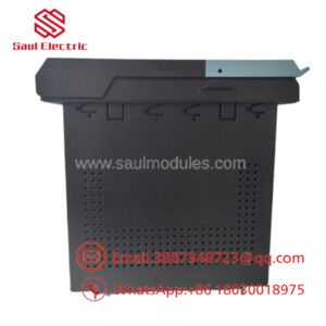
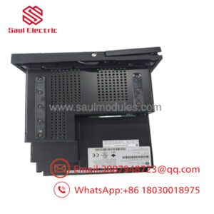
The GE VMIVME-2540 is an intelligent, high-density 128-bit Discrete Input Board developed by VMIC (a GE Fanuc company) for use within robust VMEbus architectures, including heavy-duty industrial automation and Speedtronic Mark VI turbine control systems. By packing 128 optically isolated sensing channels onto a single 6U single-slot module, this card serves as a central data collection point for massive arrays of dry contacts, field switches, limit sensors, breaker status indicators, and alarm interlocks.
Unlike standard passive input boards, the VMIVME-2540 features an integrated on-board microcontroller. This processor acts as an autonomous scanning matrix that constantly poles all 128 input states down to sub-millisecond intervals. By executing localized digital filtering and Change-of-State (COS) tracking directly on the board, it completely unburdens the master VME single-board computer from executing continuous polling operations. The card captures micro-second transition variations and holds them in local memory arrays until the primary application system requests a data frame.
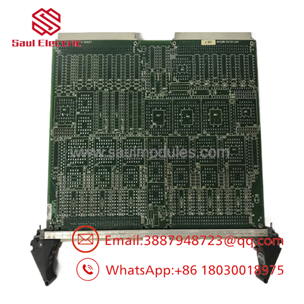
- VMIVME-2540
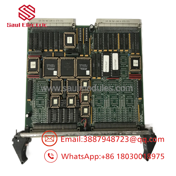
- VMIVME-2540
Installation & Configuration Guide
Stage 1: Pre-Installation Preparation (Estimated Time: 15 minutes)
- ⚠️ Safety First: The VMIVME-2540 often connects directly to high-voltage external field circuits (such as 125 VDC substation battery loops). Never remove or insert this module while the VME backplane or the external field wiring terminal arrays are energized. Lock out and tag out (LOTO) the rack power supply along with any auxiliary field interrogation power links feeding the cable harnesses.
- Tools Required: Grounded anti-static wrist strap, flathead screwdriver, long needle-nose pliers for hardware jumper adjustment, and a digital multimeter (DMM).
- Data Backup: Before swapping boards, access your VME development system console or engineering environment (such as Toolbox). Back up the specific base addressing configuration registers, VME interrupt lines (IRQ1 to IRQ7), and the precise debounce timing constant values assigned to this physical slot position.
Stage 2: Hardware Jumper Configuration (Estimated Time: 10 minutes)
- Place the new board on a static-safe workspace.
- Align the retired board next to the replacement card to match the underlying hardware settings.
- Locate the board-level configuration jumpers used to map the base memory address within the VMEbus short I/O space or standard space.
- Using needle-nose pliers, carefully replicate every hardware jumper plug sequence from the old board onto the new one. Check the jumper layout blocks controlling VMEbus interrupt level selection, geographical slot identification, and input voltage scaling thresholds.
Stage 3: Board Installation (Estimated Time: 10 minutes)
- Verify that the rear P1 and P2 pins on the VMIVME-2540 are straight, aligned, and clear of contamination.
- Open both the upper and lower injector/ejector handles on the card faceplate.
- Slide the card smoothly into the designated single-slot guide tracks inside the VME chassis enclosure.
- Push the board firmly inward until the faceplate handles meet the rack frame rails.
- Snap both ejector handles inward simultaneously to mesh the rear high-density socket pins with the backplane. Tighten the top and bottom retaining screws down securely.
- Reconnect the high-density front face communication harnesses or secure the corresponding rear transition panel cables.
Stage 4: Power-On & Commissioning (Estimated Time: 25 minutes)
- Re-engage the main VME control rack power supply breaker.
- Monitor the local diagnostic LEDs on the module faceplate:
- Power / SysFail: The power indicator should remain steady green. The system failure light (if lit red initially during self-test) must clear within 2 seconds.
- ⚠️ Troubleshooting: If the SysFail LED remains stubbornly illuminated, turn off the system and verify your base addressing jumpers to ensure no two cards are conflicting on the VME data highway.
- Boot up your target controller operating application. Check the software log output to verify that the core processing unit successfully communicates with the , and run a simple toggle test on a known input channel to confirm active data parsing.
Frequently Asked Questions (FAQ)
Can I hot-swap the card while the system is online?
No. The does not incorporate live insertion or extraction protection protocols. Pulling the module while the VME bus is energized will cause rapid voltage spikes on the shared communication paths, which can corrupt data blocks, lock up adjacent single-board computers, and permanently damage the board’s internal transceiver components. Always shut off power before executing a card replacement.
What is the specific purpose of the on-board “Debounce Filter”?
Mechanical field devices like pressure switches or heavy relay contacts do not close cleanly; they exhibit a microscopic “bouncing” behavior that can look like rapid on/off cycles to a fast microprocessor. The resolves this via its software-programmable digital debounce filter. This function requires an input state to remain steady for a set period (e.g., 5 ms to 20 ms) before validating it as a true state change, eliminating phantom signal chatter.
How do I troubleshoot a “Failed to Respond on VME Bus” software alert?
This message indicates that the master VME processor is attempting to read data from a specific memory address where it expects the to reside, but the card is not acknowledging the command. Isolate power and check your hardware jumper settings on the board. A single misplaced address jumper will shift the card’s memory location away from its software-defined project parameters.
Why do some variations of this model arrive with different input voltage ratings?
The series was built with modular factory options to accommodate varying plant environments. Depending on the exact build codes, the inputs can be scaled to look for low-voltage TTL logic levels, 24 VDC industrial loops, or high-voltage 125 VDC utility control batteries. Always double-check your original component label against the replacement unit to ensure the input voltage tolerances match your field loop outputs.
Are these VMIC cards currently supported and manufactured by GE?
Because legacy VME automation networks have transitioned toward newer distributed platform models, these cards are no longer in active serial production by the original manufacturer. Our current inventory consists of New Original / New Surplus stock—unused, pristine warehouse spares preserved from plant cancelations, warehouse buybacks, or liquidations. This provides direct access to authentic replacement parts without long lead times.

 Start Chat


