





Description
Key Technical Specifications
| Parameter | Value |
|---|---|
| Manufacturer | GE Intelligent Platforms / VMIC |
| Model | VMIVME-3125 |
| Product Type | Analog-to-Digital Converter Module |
| Form Factor | 6U VMEbus Board |
| Bus Interface | ANSI/IEEE 1014 VMEbus |
| Analog Inputs | 32 Single-Ended or 16 Differential |
| A/D Resolution | 12-bit |
| Aggregate Conversion Rate | 40 kS/s |
| Input Voltage Ranges | ±50 mV to ±10 V, 0 to +10 V (configuration dependent) |
| Current Input Option | 0 to 25 mA (optional configuration) |
| Gain Settings | x1, x10, x100 (jumper selectable) |
| Data Format | Offset Binary or Two’s Complement |
| Isolation | 1,000 V Analog-to-Digital Ground Isolation |
| Protection | Overvoltage Protection with Low-Pass Filtering |
| Built-In Test | Real-Time BIT (Built-In Test) Supported |
Product Introduction & Supply Chain Strategy
The GE VMIVME-3125 is a VME analog input module that continuously scans and converts multiple analog voltage or current signals into digital data for process control, factory automation, laboratory instrumentation, and industrial data acquisition systems. Automatic scanning minimizes processor overhead while providing continuously updated measurement data.
This product is a Brand New Surplus unit. It is not used, not pulled from a decommissioned plant, and not refurbished. All modules undergo rigorous quality verification to ensure OEM-level reliability. Since the VMIVME-3125 belongs to a mature VME platform, maintaining 1–2 units of buffer stock and implementing a last-time-buy strategy reduces Total Cost of Ownership (TCO), minimizes lead time variability, and avoids the operational risks associated with refurbished electronics.
Installation & Configuration Guide
Stage 1: Pre-Installation (Prep & Safety)
- Perform Lock-Out/Tag-Out (LOTO).
- Shut down the VME chassis and verify power removal.
- Wear a grounded ESD wrist strap.
- Photograph:
- Jumper settings
- Base address configuration
- Input wiring
- VME slot location
- Record all channel configuration parameters before removal.
Stage 2: Removal
- Disconnect all field wiring.
- Release both injector/ejector handles evenly.
- Remove the board straight along the guide rails.
- Inspect the VME connector for bent pins or contamination.
Stage 3: Installation (Clone & Seat)
- Duplicate all jumper settings exactly.
- Configure input type (single-ended, differential, or current input) as required.
- Install the module fully into the VME backplane.
- Lock both ejector handles.
- Reconnect all field wiring according to documented terminal assignments.
Stage 4: Power-On & Testing
- Verify VME power rails before energizing the chassis.
- Confirm the diagnostic LED indicates normal startup.
- Execute the Built-In Test (BIT).
- Verify analog input scaling and channel readings.
- Compare measured values with calibrated reference signals before returning the system to operation.
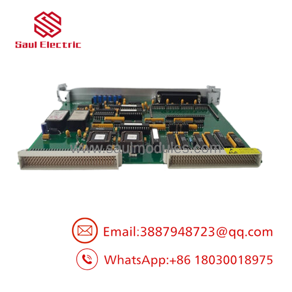
- VMIVME-3125
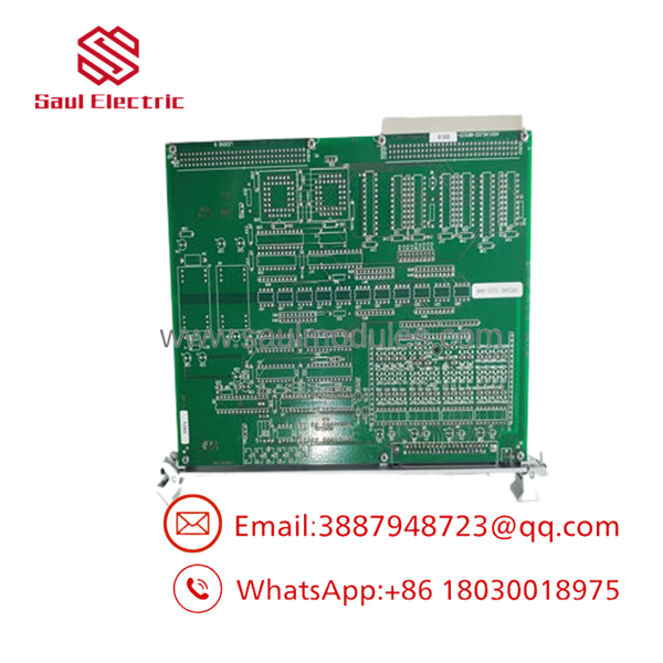
- VMIVME-3125
Firmware/Software Versions & Upgrade Notes
- The VMIVME-3125 uses jumper-based hardware configuration with minimal firmware dependency.
- Document all jumper positions before replacement to ensure identical operation.
- Verify VME base address settings and access mode compatibility with the existing control software.
- Confirm the selected data format (Offset Binary or Two’s Complement) matches the application software.
- Avoid modifying hardware configuration during emergency replacement unless the entire control system has been validated.
- Maintain backups of calibration parameters, channel mapping, and engineering documentation to simplify commissioning after replacement.
Frequently Asked Questions (FAQ)
Q1. Is this module genuinely new?
Yes. This is a New Original / New Surplus module. It is not used, repaired, or refurbished. Every unit undergoes OEM serial verification, inbound traceability inspection, electrical testing, Built-In Test (BIT) verification, and ESD-safe packaging before shipment.
Q2. Why is New Surplus priced above refurbished products but below OEM factory pricing?
Our pricing reflects the global cost of securing genuine New Surplus inventory. Although it may cost 20–30% more than refurbished alternatives, it eliminates hidden component aging, uncertain repair quality, and previous field stress that can lead to expensive unplanned downtime.
Q3. Is the obsolete?
The is a mature VME product family with declining worldwide availability. Plants operating these systems should maintain 1–2 spare modules, monitor lifecycle status, consolidate approved vendors, and execute a planned last-time-buy before inventory becomes difficult to source.
Q4. Can this module be hot-swapped?
No. Hot-swapping is not recommended. Always de-energize the VME chassis and follow plant maintenance procedures before removing or installing the module to prevent backplane damage and invalid measurement data.
Q5. Will replacing the module require software changes?
In most installations, application software remains unchanged. However, jumper settings, VME base address, input type, gain selection, and data format must exactly match the original module to maintain compatibility.
Q6. What quality verification is performed?
Every New Surplus module follows a documented SOP that includes:
- OEM packing list verification
- Serial number authentication
- Visual inspection
- Power-on diagnostics
- Built-In Test (BIT) verification
- Analog input functional testing
- Electrical insulation and continuity testing
- QC inspector approval
- ESD-safe packaging
- Heavy-duty export shipping preparation
Q7. What inventory strategy provides the lowest Total Cost of Ownership (TCO)?
For mission-critical VME control systems, maintain on-site as buffer stock. Combine lifecycle monitoring, vendor consolidation, cross-site inventory sharing, and a planned last-time-buy strategy to reduce lead time variability, avoid emergency procurement, minimize obsolescence risk, and achieve a lower Total Cost of Ownership (TCO).



 Start Chat


