





Description
Key Technical Specifications
| Parameter | Value |
|---|---|
| Manufacturer | GE Fanuc / VMIC (Abaco Systems) |
| Model | VMIVME-4140 |
| Product Type | Analog Output Board |
| Bus Interface | VMEbus |
| Output Channels | 32 analog outputs |
| Resolution | 12-bit DAC per channel |
| Maximum Output Current | ±10 mA per channel |
| Output Impedance | 0.8 Ω |
| Output Voltage Ranges | 0–2.5 V, 0–5 V, 0–10 V, ±2.5 V, ±5 V, ±10 V (software selectable) |
| Update Mode | Random (non-scanning) or synchronous update |
| Calibration | Automatic software or reset-initiated calibration |
| Diagnostics | Built-in self-test and offline output testing |
| Field Connection | Discrete wiring or mass-terminated cables |
| Status Indicator | Front-panel LED |
| Form Factor | VMEbus Eurocard |
Product Introduction
The GE VMIVME-4140 is a 32-channel, 12-bit analog output VMEbus board developed by VMIC (GE Fanuc, now Abaco Systems) for precision industrial control, automatic test equipment (ATE), and data acquisition systems. Each channel incorporates its own dedicated DAC, providing stable and deterministic analog voltage outputs without multiplexing delays.
The module supports six software-selectable voltage ranges, including both unipolar and bipolar outputs, making it suitable for driving actuators, servo systems, instrumentation, and simulation equipment. Automatic calibration routines and comprehensive onboard diagnostics improve long-term accuracy while reducing maintenance requirements. Additionally, outputs can be disconnected from field wiring during self-test, allowing offline diagnostics without disturbing external equipment.
Typical applications include:
- Industrial process control
- Power generation control systems
- Hardware-in-the-loop (HIL) simulation
- Automatic Test Equipment (ATE)
- Aerospace and defense systems
- Laboratory instrumentation
- Data acquisition and control
- VME-based embedded computing platforms

- VMIVME-4140
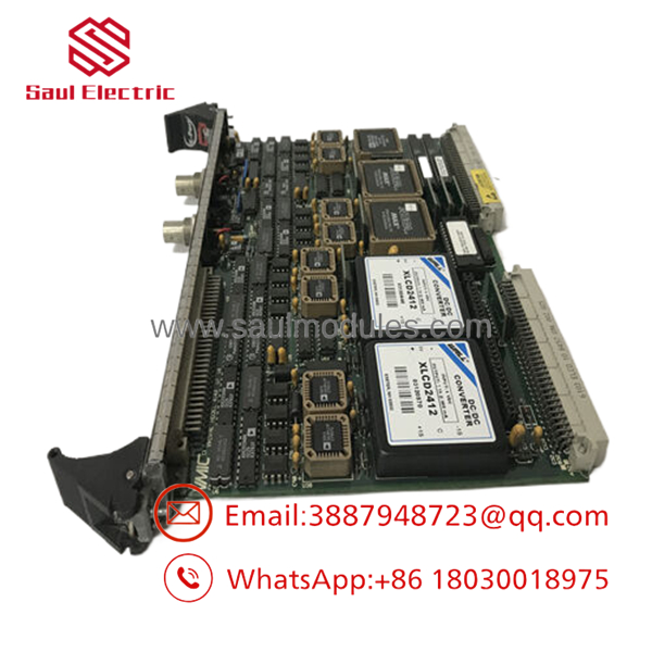
- VMIVME-4140
Troubleshooting Quick Reference
| Symptom | Possible Cause | Relevance | Quick Check Method | Recommendation |
|---|---|---|---|---|
| No analog outputs | VME communication or board power failure | ✅ High | Verify VME backplane power and address configuration | Check chassis before replacing board |
| One channel inaccurate | DAC or field wiring issue | ✅ High | Measure output using a calibrated voltmeter | Verify load and channel configuration |
| All outputs shifted | Calibration data invalid | ✅ High | Execute software calibration routine | Recalibrate board |
| Incorrect voltage range | Software configuration error | ⚠️ Medium | Verify configured output range | Select correct unipolar/bipolar range |
| Self-test failure | Internal hardware fault | ✅ High | Review diagnostic register and LED status | Replace board if failure persists |
| Output instability | Excessive load current | ⚠️ Medium | Measure load impedance | Keep output within specification |
| CPU cannot access board | VME address conflict | ⚠️ Medium | Verify address jumpers/DIP switches | Correct address assignment |
Field Tip: Most VMIVME-4140 service issues are caused by incorrect output-range configuration, calibration drift, or VME addressing conflicts rather than hardware failure. Running the onboard self-test and automatic calibration before replacing the board often restores normal operation.
Frequently Asked Questions (FAQ)
Q1. What is the primary function of the VMIVME-4140?
The provides 32 independent 12-bit analog voltage outputs for VMEbus control systems, enabling precise control of external equipment such as actuators, simulators, and instrumentation.
Q2. How many analog outputs does the board provide?
The board includes 32 independent analog output channels, with one dedicated DAC assigned to each channel.
Q3. Which voltage ranges are supported?
Software-selectable output ranges include:
- 0 to +2.5 V
- 0 to +5 V
- 0 to +10 V
- ±2.5 V
- ±5 V
- ±10 V
This flexibility allows the module to support a wide variety of industrial control applications.
Q4. Does the module support automatic calibration?
Yes. Calibration is automatically initiated after a system reset or can be started by software. Offset and gain coefficients are calculated and stored to maintain output accuracy.
Q5. Can outputs be tested without affecting field equipment?
Yes. The allows analog outputs to be disconnected from field wiring for offline self-testing, enabling diagnostics without disturbing connected devices.
Q6. Is the still available?
The product entered Restricted Production Phase (RPP) in 2019 and is now considered a legacy platform. Most available units are supplied as New Surplus, refurbished, or professionally tested spare parts.
Q7. What should I verify before installation?
Engineers should confirm:
- Complete model number ()
- VME chassis compatibility
- VME address configuration
- Selected output voltage ranges
- Output load requirements
- Calibration status
- Field wiring integrity
- System grounding
- ESD protection during installation
Performing these checks before commissioning helps ensure accurate analog output performance and reliable operation in mission-critical VME control systems.



 Start Chat


