





Description
Key Technical Specifications
| Parameter | Value / Specification |
|---|---|
| System Architecture | Standard 6U VMEbus Architecture (VME64 compliant) |
| Network Framework | Reflective Memory Replicated Shared Network |
| Data Transfer Rate | Up to 29.5 Megabytes per second continuous throughput |
| Connection Media | Multi-mode fiber-optic cabling (ST connectors) |
| Node Distance Capacity | Up to 1,000 feet (300m) between nodes; up to 10,000 feet total network length |
| Network Topology | Unidirectional Ring configuration |
| Memory Configurations | Onboard SDRAM options up to 256 MB |
| Dynamic Latency | Sub-microsecond local writing latency; low-latency propagation |
| Error Handling | Redundant transmission checking with automatic parity fault detection |
| Interrupt Control | 4 software-programmable network interrupt levels |
| Operating Temperature | 0 to +65°C (32 to 149°F) standard industrial operational window |
Product Introduction
The GE VMIVME5576 is an intelligent, high-speed Reflective Memory Interface Board developed by VMIC (a GE Fanuc company) for 6U VMEbus distributed control systems, including GE Speedtronic Mark VI turbine control platforms and heavy-duty Hardware-in-the-Loop (HILS) simulation clusters. This module acts as an ultra-fast, real-time shared memory network node that allows multiple independent computer systems to share a single, identical memory image over a deterministic fiber-optic ring network.
Unlike standard token-ring or Ethernet protocols that require software stack handshaking and packet overhead processing, the VMIVME5576 handles replication entirely at the hardware level. When a local VME host processor writes a byte of data to its onboard Reflective Memory partition, the card’s internal logic instantly serializes that data frame and flashes it down the fiber-optic transmit line. The downstream nodes receive the packet, update their identical local memory arrays within microseconds, and pass the data along. This hardware-driven synchronization provides predictable, real-time data pooling across distributed nodes without taxing main CPU processor bandwidth.
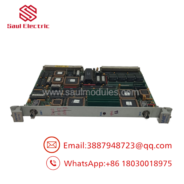
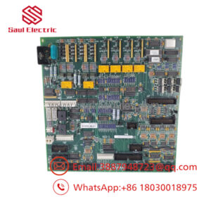
- VMIVME5576
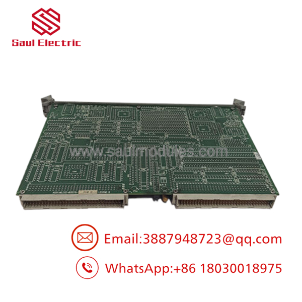
- VMIVME5576
Installation & Configuration Guide
Stage 1: Pre-Installation Preparation (Estimated Time: 15 minutes)
- ⚠️ Safety First: The VMIVME5576 card bridges high-speed data structures across runtime controllers. Never insert or extract this module while the VME backplane is energized. Bring the process system to a verified, safe standby state, and execute a complete lock out/tag out (LOTO) on the master control power distribution breaker feeding the card cage enclosure.
- Tools Required: Grounded anti-static prevention wrist strap, fine needle-nose pliers for micro-jumper adjustments, flathead screwdriver, and fiber-optic cleaning swabs.
- Data Backup: Access your engineering workstation or software project tree (such as Toolbox). Back up the memory-mapped short or standard I/O base addresses, network node ID variables, and designated interrupt vectors (IRQ1 to IRQ7) mapped to this physical slot position.
Stage 2: Hardware Jumper & Node ID Assignment (Estimated Time: 10 minutes)
- Lay the replacement module down on a clean, static-safe workspace.
- Place the retired module alongside it to match board configurations.
- Locate the physical jumper blocks used to establish the VMEbus base memory address and geographical slot assignments.
- Locate the specific Node ID Jumper Matrix on the board. Each card in a Reflective Memory ring must be assigned a unique Node ID number (from 1 up to 255). Program the replacement unit’s jumpers to match the exact Node ID of the card being retired.
Stage 3: Board Insertion & Fiber Patching (Estimated Time: 10 minutes)
- Verify that the rear P1 and P2 backplane pin rows are straight and clear of debris.
- Open both the top and bottom mechanical injector/ejector handles on the card faceplate.
- Slide the board smoothly along the channel guide tracks into its designated single-slot position.
- Press both ejector handles inward simultaneously until they lay flush, seating the card firmly into the VME backplane socket. Secure the upper and lower faceplate retaining screws.
- Remove the protective dust caps from the ST fiber-optic ports. Clean the fiber ends using specialized swabs and connect the cables: Fiber Out (TX) of the preceding node lands on Fiber In (RX) of this module.
Stage 4: Power-On & Loop Commissioning (Estimated Time: 20 minutes)
- Re-engage the main VME rack control circuit breaker.
- Monitor the diagnostic lights on the module faceplate:
- Power / Board Healthy: Should stabilize into a steady green indicator.
- Link Activity: Indicates that the fiber-optic carrier signal is complete and receiving light pulses from the upstream neighbor.
- ⚠️ Troubleshooting: If the link activity indicator remains unlit, check for a broken fiber line or swapped TX/RX patches along your ring topology.
- Boot up your target control framework. Run a local diagnostic memory write command from your development console to verify that adjacent nodes mirror the state change instantly, confirming active network data replication.
Frequently Asked Questions (FAQ)
Can I hot-swap the VMIVME5576 board while the rest of the network is active?
No. The does not possess live insertion or hot-swap circuitry. Extracting the card while the rack is powered can cause an electrical short across the VME backplane, data corruption in neighboring modules, and physical failure of the board’s transceiver. Additionally, removing a card breaks the physical fiber-optic ring network, causing a loss of communication across all down-ring nodes and leading to a widespread system trip.
What happens to the network if a single node completely loses control power?
The features a built-in hardware-level mechanical bypass relay or specialized fallback circuit designed to bridge the network layer under specific fault conditions. However, a total power loss at a node can disrupt the active amplification of the optical loop. In high-reliability configurations, it is best practice to implement external optical bypass switches to route data around a dark or unpowered cabinet automatically.
Why does the software display a “Reflective Memory Parity Error” log message?
A parity error indicates that data was corrupted while traveling across the fiber-optic cable ring between nodes. This is typically caused by dirty fiber-optic ST connectors, a pinched or over-bent fiber patch cord, an aging laser diode transmitter on the upstream board, or excessive electromagnetic interference along poorly isolated cable runs. Clean the fiber terminations using optical swabs and check cable routing bends to clear the fault.
What is the purpose of assigning a unique “Node ID” to each card?
Reflective Memory works by passing data packets continuously down a unidirectional ring. When a card transmits a write command, that packet travels through every subsequent node in the ring. The unique Node ID allows the originating card to recognize its own data packet when it completes the full circle. Once the packet returns to its source node, the board drops it from the loop to prevent infinite data looping.
Why are these specialized VMIC modules sold primarily as “New Surplus”?
Because the legacy VMEbus architecture has evolved through subsequent generations and distributed network upgrades, these specific VMIVME series cards are no longer in active serial production by the OEM. Our inventory consists of New Original / New Surplus units—unused, pristine factory spares sourced from plant liquidated overstocks, canceled infrastructure builds, or warehouse reserves. This provides direct access to authentic replacement parts without long production lead times.

 Start Chat


